
AR 15 Parts Diagram | AR 15 Parts List
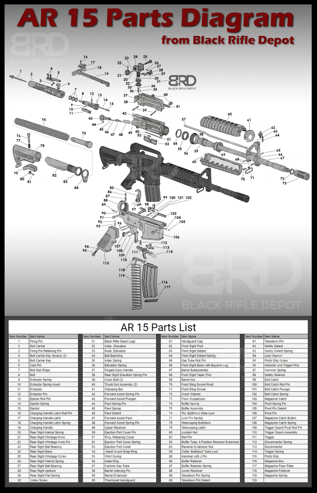
The Complete AR 15 Parts Diagram with AR 15 Parts List and all AR 15 Parts Labeled
AR 15 Parts Diagram | AR 15 Parts List
The AR-15 Parts Diagram is an essential visual guide that breaks down the intricate components of this popular rifle platform. It provides a comprehensive understanding of how each part interacts with others to form a functional and reliable firearm. From the upper and lower receivers to the bolt carrier group, gas system, and trigger assembly, the diagram highlights the key elements that make up the AR-15's design. Whether you're a firearm enthusiast, a gunsmith, or a first-time owner, this diagram serves as an invaluable reference, aiding in maintenance, customization, and troubleshooting to ensure optimal performance of your AR-15. For more in-depth information on how to build an AR-15, please check out our other comprehensive guide available on our blog.
1. Firing Pin
The AR-15 firing pin is an essential element in the operation of firearms, serving as the catalyst for the ignition process that discharges a cartridge. This slender, yet crucial component plays a central role in the firing sequence by impacting the cartridge's primer, thus sparking the combustion needed to launch the projectile.
- Material: Firing pins are typically crafted from 8740 hardened steelor stainless, allowing them to endure the impact against the primer without deforming, ensuring longevity and consistent performance.
- Function: Its primary function is to transfer the hammer or striker's force directly to the cartridge's primer, igniting the gunpowder within. This ignition is what propels the bullet or projectile through the barrel and towards the target.
- Role in Operation: In the firearm's firing cycle, the firing pin is indispensable. Without it, the chain reaction required to fire a round cannot commence. The design and proper functioning of the firing pin are critical for the firearm's accuracy, as any inconsistency in the pin's impact can affect the bullet's trajectory.
- Maintenance: Regular maintenance is vital to ensure the firing pin remains functional. It should be inspected routinely for signs of wear, damage, or build-up of residues, which could impede its performance and, consequently, the firearm's reliability.
The design and condition of the firing pin are paramount in ensuring the firearm operates effectively, underscoring the importance of this component in the overall mechanics and safety of the weapon.
- Mil-Spec Firing Pin: Adheres to military specifications, offering enhanced durability and reliability, essential in combat conditions.
- Extended Firing Pin: A longer design ensures consistent contact with the primer, especially in modified firearms where standard pins may not provide reliable ignition.
Understanding these aspects underscores the firing pin's significance in firearm functionality and the necessity of proper maintenance to uphold safety and performance.
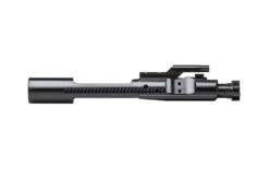
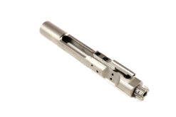
2. Bolt Carrier
The AR-15 bolt carrier is a pivotal component in many firearms, notably in semi-automatic and automatic rifles, playing an essential role in the firearm's cycling process, which includes ejecting spent cartridges and chambering new rounds.
-
Material: Bolt carriers are typically crafted from robust materials like 158 Carpenter steel, 8620 steel, or 9310 steel, each chosen for its specific properties:
- 158 Carpenter Steel: Known for its exceptional strength and durability, ideal for high-stress components.
- 8620 Steel: Offers good strength and toughness, commonly used in the construction of bolt carrier groups due to its balanced performance.
- 9310 Steel: Superior strength and wear resistance, often used for critical parts that require high durability and resilience.
- Function: The bolt carrier facilitates the movement of the bolt, enabling the extraction of spent cartridges and loading of new ones, which is crucial for the firearm's operation and rapid firing capability.
- Role in Operation: It is central to the efficient cycling of the firearm, ensuring the weapon can fire, eject, and reload smoothly and reliably.
-
Maintenance: Regular maintenance is necessary to keep the bolt carrier in optimal condition. This includes cleaning to remove debris and prevent build-up, as well as inspecting for wear or damage, especially given the high-stress nature of its function.
- Bolt Carrier Body: This is the primary section of the bolt carrier, designed to house and protect the smaller, more intricate components of the bolt carrier group, ensuring cohesive operation.
- Black Nitride BCG: A favored finish for bolt carriers, black nitride enhances durability, provides excellent corrosion resistance, and reduces friction, which contributes to smoother operation and less need for frequent lubrication.
3. Firing Pin Retaining Pin
The firing pin retaining pin is a small, yet indispensable component in the assembly of many firearms, playing a critical role in securing the firing pin's position within the bolt carrier. This pin is essential for maintaining the correct placement and operational integrity of the firing pin, ensuring the firearm functions as intended.
- Material: Typically crafted from sturdy materials, the firing pin retaining pin is built to withstand the forces exerted during the firing process, ensuring durability and sustained effectiveness.
- Function: Its main function is to hold the firing pin securely within the bolt carrier, preventing any lateral or longitudinal movement that could disrupt the firing pin's alignment or proper function.
- Role in Operation: By maintaining the firing pin's correct positioning, the retaining pin ensures that the firing pin strikes the primer with the necessary precision and force, facilitating the ignition of the cartridge. This precision is crucial for the reliability and safety of the firearm's operation.
- Maintenance: Regular inspection and maintenance of the firing pin retaining pin are essential to ensure its integrity and functionality. Checking for wear, damage, or improper fit is crucial to prevent malfunctions or inconsistencies in the firearm's performance.
The firing pin retaining pin, though small, is vital to the firearm's overall reliability and accuracy, underscoring the importance of each component, no matter the size, in the complex mechanism of a firearm.
4. Bolt Carrier Key Screws
The bolt carrier key screws are essential components within the bolt carrier group (BCG) of many firearms, particularly in gas-operated systems. These screws play a pivotal role in securing the bolt carrier key (also known as the gas key) to the bolt carrier, ensuring that the entire assembly functions cohesively and efficiently.
- Material: Typically made from high-strength steel, bolt carrier key screws are designed to withstand the high pressures and mechanical stresses encountered during the firearm's operation, ensuring durability and reliability.
- Function: Their primary function is to fasten the bolt carrier key firmly to the bolt carrier. The bolt carrier key is a crucial part of the gas-operated system, channeling the gas used to cycle the firearm. The screws ensure that the key remains securely attached to the carrier, preventing gas leaks and ensuring proper cycling of the firearm.
- Role in Operation: In gas-operated firearms, the bolt carrier key interacts directly with the gas system. When a round is fired, gas is funneled through the gas tube and into the bolt carrier key. The secure attachment provided by the screws ensures that this gas is efficiently used to push the bolt carrier, facilitating the extraction and ejection of the spent cartridge and the chambering of a new round. This process is critical for the semi-automatic or automatic operation of the firearm.
- Maintenance: Regular inspection and maintenance of the bolt carrier key screws are crucial. They should be checked for proper torque, signs of wear, or damage. Loose or damaged screws can lead to gas leaks or malfunctions, compromising the firearm's performance and safety.
The bolt carrier key screws are, therefore, integral to the proper function and maintenance of the bolt carrier group in gas-operated firearms, underscoring the importance of every component, no matter how small, in the overall mechanism and reliability of the firearm.
5. Bolt Carrier Key
The bolt carrier key, also known as the gas key, is a critical component in the bolt carrier group (BCG) of gas-operated firearms. It plays an essential role in harnessing the gas pressure to cycle the firearm effectively, connecting the gas system's energy to the firearm's mechanical cycling process.
- Material: The gas key is typically made from 8740 steel, designed to withstand high temperatures and pressures generated by the gas system, ensuring durability and reliability throughout its operational life.
- Function: Its primary function is to channel the hot gas from the fired cartridge, delivered via the gas tube, into the bolt carrier. This gas pressure is what drives the bolt carrier rearward, initiating the extraction and ejection of the spent cartridge case, the re-cocking of the hammer, and the chambering of a new round.
- Role in Operation: The gas key's role is pivotal in the operation of gas-operated firearms. It ensures that the energy generated by the gas system is efficiently transferred to the bolt carrier group, enabling the automated cycling process essential for semi-automatic and automatic firing modes.
- Maintenance: Proper maintenance of the gas key is crucial for the firearm's reliability and safety. This includes ensuring that the gas key is securely attached to the bolt carrier, checking for signs of wear or damage, and ensuring that its internal passage is clean and unobstructed to allow free flow of gas.
The bolt carrier key's functionality is integral to the performance of gas-operated firearms, highlighting its importance in ensuring the effective and reliable operation of the weapon's cycling mechanism.
6. Cam Pin
The cam pin is a crucial element in the bolt carrier group (BCG) of many firearms, especially those with a rotating bolt design, such as in many modern rifles. This component plays a vital role in the mechanical cycling of the firearm, ensuring the correct sequence of locking and unlocking the bolt.
- Material: Typically made from high-strength steel, the cam pin is built to endure the stresses and strains of the firearm's cycling process, ensuring durability and reliability throughout its operational life.
- Function: The cam pin fits through a hole in the bolt and sits within the bolt carrier. Its primary function is to interact with the bolt carrier and the bolt, facilitating the rotational movement necessary for the bolt to lock into the barrel extension or unlock from it. As the bolt carrier moves within the receiver, the cam pin rotates the bolt, engaging or disengaging it with the locking lugs in the barrel extension.
- Role in Operation: During the firing cycle, the cam pin's rotation is essential for the timing and execution of the bolt's locking and unlocking phases. This process is critical for ensuring the firearm's safety and functionality, as it allows the bolt to secure firmly during firing and unlock for the ejection and chambering of rounds.
- Maintenance: Regular inspection and maintenance are crucial for the cam pin's longevity and the firearm's overall reliability. Wear, damage, or improper lubrication can affect its function, potentially leading to malfunctions or increased wear on other components.
The cam pin's efficient operation is integral to the proper function of the firearm's cycling mechanism, highlighting its importance in the overall performance and safety of the weapon. Ensuring that this component is in good working condition is essential for maintaining the firearm's functionality and reliability.
7. Bolt Gas Rings
Bolt gas rings, essential components in gas-operated firearms, play a pivotal role in ensuring the efficient and safe operation of the weapon. These rings are integral to maintaining the necessary seal within the bolt carrier group (BCG), which is crucial for the firearm's cycling process.
- Material: Bolt gas rings are usually made from durable materials capable of withstanding high temperatures and pressures, such as steel or other resilient metal alloys. Their material composition ensures they maintain their sealing properties even under the intense conditions of rapid firing.
- Function: The primary function of bolt gas rings is to seal the space between the bolt and the bolt carrier. This seal is vital for directing the gas energy into moving the BCG to cycle the firearm. When a round is fired, gas is funneled back into the BCG, and the gas rings ensure this gas does not escape, pushing the bolt carrier to the rear and facilitating the extraction and ejection of the spent cartridge, cocking of the hammer, and chambering of a new round.
- Role in Operation: Without effective gas rings, the firearm could fail to cycle correctly, as the necessary gas pressure would not be adequately maintained. The seal created by the gas rings ensures that the gas generated by the fired round is utilized to its full potential, enabling the firearm to function reliably and efficiently.
- Maintenance: Regular inspection and replacement of bolt gas rings are essential for maintaining the firearm's performance. Worn or damaged gas rings can lead to decreased performance and reliability, as they may not maintain the required seal, resulting in failures to cycle properly.
The functionality of bolt gas rings is crucial for the consistent and reliable operation of gas-operated firearms. Their ability to maintain a proper seal within the BCG is fundamental to leveraging the gas energy necessary for the cycling action, underscoring their importance in the overall mechanism of the weapon.
8. Bolt
9. Extractor Spring
The extractor spring is a small but crucial component in the operation of many firearms, playing a vital role in the extraction process during the firearm's cycling operation. This spring ensures the consistent and reliable removal of spent cartridge casings after firing.
- Material: Extractor springs are typically made from high-quality spring steel or similar resilient materials, designed to maintain tension and elasticity through repeated cycles of compression and expansion, ensuring longevity and consistent performance.
- Function: The primary function of the extractor spring is to provide the necessary tension to the extractor, enabling it to grip and retain the rim of the cartridge casing firmly. Upon firing, this tension allows the extractor to pull the spent casing from the chamber and facilitate its ejection from the firearm, making way for the next round to be chambered.
- Role in Operation: In the firearm's cycling process, the extractor spring's role is essential for the smooth and uninterrupted operation of the firearm. It directly influences the reliability of the extraction and ejection phases, which are critical for the firearm's readiness to fire subsequent shots.
- Maintenance: Regular maintenance is vital to ensure the extractor spring's effectiveness and longevity. Inspecting the spring for signs of wear, fatigue, or damage and replacing it when necessary helps maintain the firearm's extraction reliability and overall performance.
The functionality of the extractor spring is crucial for the consistent and reliable operation of the firearm's extraction mechanism, underscoring its importance in the overall cycling process and effectiveness of the firearm.
10. Extractor Spring Insert
The extractor spring insert, a subtle yet significant part of the bolt assembly in many firearms, plays a vital role in the functionality and longevity of the extractor mechanism. Despite its small size, its contribution to the extractor's performance is substantial.
- Material: Typically made from durable materials like polymer, the extractor spring insert is engineered to endure repetitive stress and maintain its structural integrity, ensuring it enhances the extractor mechanism's reliability over time.
- Function: The primary function of the extractor spring insert is to provide consistent support and tension for the extractor spring. It helps in distributing the spring's force more evenly, reducing the likelihood of spring fatigue or failure. This insert ensures that the extractor maintains optimal contact with the cartridge, facilitating reliable extraction of the spent casing.
- Role in Operation: In the bolt assembly, the extractor spring insert is crucial for maintaining the precise tension required for the extractor to function effectively. By enhancing the spring's performance, the insert ensures that the extractor mechanism operates smoothly, contributing to the firearm's overall reliability, particularly during the critical phases of extraction and ejection.
- Maintenance: While the extractor spring insert is designed for durability, regular inspection is recommended to ensure it remains in good condition and functions as intended. Checking for wear, deformation, or damage is essential to maintaining the extractor mechanism's efficiency and the firearm's operational reliability.
The extractor spring insert, though small, is instrumental in optimizing the extractor's performance, highlighting its importance in the effective and reliable operation of the firearm's bolt assembly.

11. Extractor
The extractor is a vital element in the bolt assembly of firearms, especially significant in semi-automatic and automatic weapons. It's a key player in the firearm's cycling process, ensuring the smooth and reliable transition through the various phases of operation.
- Material: Extractors are typically made from high-strength steel or similar durable materials, designed to withstand the stress of constant use and to effectively grip and extract cartridge casings without wearing down or failing.
- Function: The primary role of the extractor is to hook onto the rim of the cartridge casing after a round is fired, pulling the spent casing out of the chamber as the bolt moves rearward. This action is crucial for clearing the chamber to allow a new cartridge to be loaded, facilitating continuous firing.
- Role in Operation: In the operation cycle of a firearm, the extractor's role is central to the extraction phase, which is integral to the overall cycling process. A reliable extractor ensures that spent casings are consistently and efficiently removed from the chamber, preventing malfunctions that could impede the firearm's operation.
- Maintenance: Regular maintenance is essential for the extractor, ensuring it remains in good working condition. Inspecting the extractor for wear, ensuring it maintains proper tension, and cleaning it to remove any built-up residue are all crucial steps in preserving its functionality and, by extension, the reliability of the firearm.
The extractor's functionality is critical for the firearm's ability to perform its basic operations of feeding, firing, and ejecting cartridges, underscoring its importance in the mechanics of semi-automatic and automatic weapons. Ensuring its reliability is paramount for the overall performance and safety of the firearm.
12. Extractor Pin
The Charging Handle Latch Roll Pin is an essential component in the functionality of firearms that are equipped with charging handles. This small but vital piece plays a significant role in the mechanical operation of the firearm, ensuring the charging handle operates smoothly and efficiently.
- Material: Typically crafted from high-strength steel or similar durable materials, the Charging Handle Latch Roll Pin is designed to endure the wear and tear of regular use, maintaining its shape and structural integrity to provide consistent performance throughout its lifespan.
- Function: The primary role of this pin is to secure the charging handle latch in place, allowing it to pivot as needed. This pivotal action is crucial for the charging handle's operation, enabling the user to cock the firearm and prepare it for firing or clearing malfunctions.
- Role in Operation: In the overall mechanism of the firearm, the Charging Handle Latch Roll Pin is fundamental to ensuring that the charging handle functions correctly. It ensures the latch is securely attached and able to move as required, which is vital for the firearm's operation, whether for loading, clearing a jam, or performing maintenance.
- Maintenance: Regular inspection and maintenance are key to ensuring the Charging Handle Latch Roll Pin remains in optimal condition. Checking for wear, ensuring it's properly seated, and replacing it if necessary are important steps in maintaining the firearm's functionality and user safety.
The Charging Handle Latch Roll Pin, while small, is a testament to the precision engineering involved in firearm design, demonstrating how even the smallest components are crucial for the reliable and safe operation of the weapon.
13. Ejector Roll Pin
The ejector roll pin is a critical component within the bolt mechanism of a firearm, serving as a retaining pin that ensures the ejector remains correctly positioned for the firearm's optimal operation. This pin is instrumental in keeping the ejector securely in place, enabling it to perform its vital function during the firearm's cycling process.
- Material: Constructed from durable materials, typically high-strength steel, the ejector roll pin is designed to endure the stresses and strains associated with the rapid movements and forces within the bolt mechanism, ensuring long-term reliability and stability.
- Function: The primary role of the ejector roll pin is to secure the ejector within the bolt assembly. The ejector, under the tension of its spring, plays a crucial role in contacting and expelling spent cartridges from the firearm. The pin ensures that the ejector is precisely positioned to apply the necessary force to eject the casing efficiently after each shot.
- Role in Operation: In the firearm's operational cycle, the ejector roll pin is vital for the consistent performance of the ejection process. By maintaining the ejector's correct alignment and position, the pin ensures that spent cartridges are reliably ejected, facilitating smooth and uninterrupted operation, which is essential for the firearm's readiness for the next action.
- Maintenance: Proper maintenance of the ejector roll pin is essential for the firearm's overall performance and reliability. Regular inspection for wear, proper seating, and potential deformation is crucial to prevent malfunctions that could arise from a compromised ejector function.
The ejector roll pin, while small and unassuming, plays a crucial role in the mechanical efficiency and operational reliability of a firearm, underscoring the importance of every component, no matter the size, in the intricate mechanism of firearms.
14. Ejector Spring
The ejector spring is a small yet essential part of a firearm's firing mechanism, playing a vital role in the ejection of spent cartridges. It operates in tandem with the extractor, providing the necessary force to expel spent rounds from the firearm. This action is critical for the rapid clearing of the chamber, facilitating quick reloading and ensuring the continuity of the firing cycle. The reliability of the ejector spring directly influences the firearm's ability to avoid jams and maintain consistent firing.
- Material: Constructed from high-tensile strength materials, the ejector spring is designed to withstand the demands of repeated compressions and expansions, maintaining its structural integrity over time.
- Function: The primary role of the ejector spring is to supply the force required to propel spent cartridges from the firearm, a key factor in the weapon's ability to function smoothly and efficiently.
- Role in Cycling: The ejector spring is critical in the ejection phase of the firearm's operation, playing a central role in ensuring that the chamber is cleared quickly, allowing for the next round to be chambered without delay.
- Maintenance: Regular checks are crucial for the ejector spring to ensure it retains its tension and structural integrity, which are essential for consistent and effective performance.
Understanding the importance of the ejector spring and maintaining it properly are vital for the optimal functioning of a firearm, emphasizing the significance of each component, no matter how small, in the overall mechanism of the weapon.
15. Ejector
The ejector is a crucial component in the operation of semi-automatic and automatic firearms, playing a key role in the ejection process. It works in concert with the ejector spring, applying the necessary force to remove spent casings from the firearm. This process begins when a round is fired and the extractor holds the spent casing. The firearm's action compresses the ejector spring, and upon release, the ejector hits the base of the casing at a precise point, leveraging the spring's energy to eject the casing through the port. This efficient ejection is vital for the firearm's ability to perform rapid, reliable firing, ensuring seamless reloading and a consistent firing sequence.
- Material: The ejector is made from robust materials, enabling it to endure the significant forces and impacts encountered during the ejection of casings.
- Function: It employs the energy from the ejector spring to forcefully remove spent casings from the firearm, an essential action for the weapon's efficient reloading and continuous firing capabilities.
- Role in Cycling: The ejector is integral to the ejection phase of the firearm's operation cycle, playing a pivotal role in clearing the chamber quickly and preparing the weapon for the subsequent round, thus contributing to the firearm's speed and reliability in firing.
- Maintenance: Regular inspections are necessary to ensure the ejector continues to function correctly and effectively, helping to prevent any ejection issues that could interrupt the firearm's operation.
Understanding and maintaining the ejector's condition is crucial for the consistent performance and reliability of semi-automatic and automatic firearms, highlighting the importance of each component in the overall functionality of the weapon.
16. Charging Handle Latch Roll Pin
The Charging Handle Latch Roll Pin is a critical component in firearms that feature charging handles, playing a pivotal role in their functionality. This small pin has a dual purpose: it secures the latch to the charging handle and acts as a pivot point for the latch's movement, both of which are crucial for the smooth operation of the charging handle. This, in turn, is essential for efficiently cocking the firearm and ensuring it is ready for use. Despite its small size, the pin's function is significant in maintaining the firearm's reliability and performance.
- Material: The pin is crafted from durable materials, designed to withstand the rigors of repeated use and maintain its integrity over time, ensuring the longevity of the charging handle mechanism.
- Function: It serves to anchor the latch securely to the handle, providing a pivot point that allows for the latch's necessary movement. This function is crucial for the smooth and effective operation of the charging handle, enabling the user to cock the firearm efficiently.
- Role in Operation: The pin is vital for the correct functioning of the charging handle, a key component in preparing the firearm for action. Its proper operation is essential for the firearm's readiness and overall performance.
- Maintenance: Regular maintenance is required to ensure the pin is not worn or loose, which is essential for preserving the firearm's operational integrity. Regular checks help prevent potential malfunctions and ensure the charging handle operates as intended.
Maintaining the Charging Handle Latch Roll Pin in optimal condition is crucial for the effective and reliable operation of firearms with charging handles, highlighting the importance of even the smallest components in the overall functionality of the weapon.
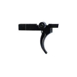
17. Charging Handle Latch
The Charging Handle Latch is a pivotal element in firearms, particularly in those with an independent charging handle. Its main role is to release the charging handle from the receiver, enabling the handle to be retracted. This retraction is a vital action for cocking the firearm or clearing it. The latch guarantees that this operation is both secure and straightforward, offering a dependable method for users to engage the charging handle as needed. Its design and operational efficiency are crucial for the firearm's effective and safe use.
- Material: Crafted from 7075-T6 aluminum to withstand regular engagement and ensure durability.
- Function: Allows the disengagement of the charging handle from the receiver, facilitating essential actions like cocking or clearing the firearm.
- Role in Operation: Ensures the secure and smooth operation of the charging handle, critical for the firearm's readiness and safety.
- Maintenance: Regular checks are necessary to ensure its proper function and structural integrity, maintaining the firearm's overall performance and safety.
18. Charging Handle Latch Spring
The charging handle latch spring is a crucial component in firearms, providing the necessary tension to keep the charging handle latch in place during use. This spring plays a vital role in the manual operation of the bolt or bolt carrier, which is essential for the firearm's safe and efficient functioning. The integrity and performance of this spring are directly linked to the reliability of the charging handle, ensuring it remains securely positioned throughout the firearm's operation.
- Material: Constructed from high-quality spring steel to maintain consistent tension and durability.
- Function: Delivers the required tension to the latch, securing the charging handle in the correct position for reliable operation.
- Role in Operation: Essential for the smooth and secure manual operation of the charging handle, affecting the firearm's safety and efficiency.
- Maintenance: Needs periodic inspection to ensure it maintains its tension and integrity, preventing operational failures.
19. Charging Handle
The AR-15 charging handle is the central element of the charging handle assembly in a firearm, acting as the core structure around which the assembly is constructed. Its function is to enable the manual manipulation of the firearm's bolt or bolt carrier, which is key for cocking the weapon, addressing malfunctions, or preparing it to fire. The design and user-friendliness of the charging handle are vital for the effective and safe use of the firearm, offering the shooter a dependable method to manually operate the firearm's action.
- Material: Made from s7075-T6 aluminum alloy to withstand the rigors of repeated use and provide a long service life.
- Function: Allows for the manual engagement and operation of the bolt or bolt carrier, essential for chambering a round, clearing jams, or preparing it for use.
- Role in Operation: Central to the user's ability to interact with the firearm's mechanical action, influencing the ease and safety of operation.
- Maintenance: Requires regular inspection and cleaning to ensure it operates smoothly and maintains its structural integrity.
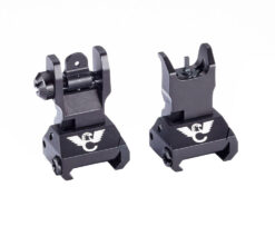
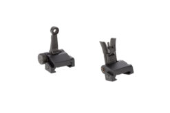
20. Rear Sight Helical Spring
The rear sight helical spring is an essential part of a firearm's sighting system, designed to apply steady tension on the sight bearing located in the windage adjustment knob. This spring is crucial for maintaining the rear sight's precise and stable positioning, enabling shooters to adjust and align the sight accurately for precise targeting. Its helical structure is crafted for endurance and consistent performance, ensuring the sight's alignment remains intact through numerous recoils and adjustments, thus preserving the firearm's long-term accuracy.
- Material: Constructed from resilient materials to ensure it can withstand the forces of adjustment and recoil while maintaining its shape and tension.
- Function: Provides the necessary tension to the sight bearing, aiding in precise and stable windage adjustments of the rear sight.
- Role in Operation: Key to the accurate and reliable adjustment of the rear sight, contributing to the overall aiming and shooting accuracy of the firearm.
- Maintenance: Needs regular inspection to ensure it remains in good condition and functions correctly, preserving the firearm's accuracy.


21. Rear Sight Windage Knob
The rear sight windage knob is a crucial component of a firearm's aiming system, specifically crafted to allow for precise lateral adjustments of the rear sight. This knob facilitates the shooter's ability to make fine-tuned adjustments to the sight's alignment, counteracting the effects of windage, or the horizontal deviation in the bullet's path caused by crosswinds. Through the manipulation of the windage knob, shooters can refine their aim, significantly improving the firearm's accuracy and performance. This adjustment capability is essential for maintaining optimal aiming precision, especially when shooting over long distances or in changing wind conditions.
- Material: Made from robust materials to endure frequent adjustments and maintain its functional integrity.
- Function: Enables precise lateral adjustments of the rear sight to correct for horizontal discrepancies in the bullet's trajectory.
- Role in Operation: Vital for fine-tuning the firearm's aim, allowing shooters to compensate for windage and enhance accuracy.
- Maintenance: Requires consistent monitoring and maintenance to ensure it remains accurate and responsive to adjustments.
22. Rear Sight Windage Knob Pin
The Rear Sight Windage Knob Pin plays a pivotal role in a firearm's rear sight assembly, serving as the connecting element that secures the windage knob to the windage screw. This pin is essential for ensuring that rotations of the windage knob are accurately conveyed to the sight aperture, facilitating its movement to the left or right as needed. Such a mechanism is crucial for the precise lateral adjustments of the sight, allowing shooters to fine-tune the firearm's alignment for windage compensation or accurate target acquisition. The absence of this pin would disrupt the transfer of adjustments from the knob to the sight, significantly affecting the firearm's aiming precision.
- Material: Constructed from durable material to ensure secure attachment and enduring functionality.
- Function: Links the windage knob to the windage screw, enabling accurate translation of adjustments to the sight aperture.
- Role in Operation: Fundamental for the accurate lateral adjustment of the rear sight, critical for precise aiming and accuracy enhancement.
- Maintenance: Regular inspection is necessary to ensure it remains securely in place and functions correctly, maintaining the firearm's accuracy.
23. Rear Sight Ball Bearing
The Rear Sight Ball Bearing is an integral part of the rear sight mechanism on a firearm, playing a key role in its functionality. This small but crucial component is designed to exert consistent tension on the windage knob, ensuring that once the knob is adjusted to the desired setting, it remains securely in place. This stability is vital for preventing any unwanted movement that could impact the firearm's aiming accuracy.
- Material: The ball bearing is constructed from high-quality materials that are chosen for their durability and ability to withstand the demands of repeated use, thereby ensuring the longevity of the rear sight mechanism.
- Function: Its primary function is to maintain steady tension on the windage knob, which is essential for keeping the knob—and thus the sight—fixed in the chosen position. This ensures that the adjustments made to the sight remain unchanged, preserving the accuracy of the firearm over time and under various conditions.
- Role in Operation: The Rear Sight Ball Bearing is crucial for the precise operation of the rear sight, enabling shooters to make reliable and stable adjustments to their aim. Its effectiveness directly influences the consistency and reliability of the firearm's accuracy.
- Maintenance: To ensure its continued performance and reliability, regular maintenance of the ball bearing is essential. This includes checking for wear and ensuring that it remains in good condition, as any degradation could affect the rear sight's stability and the firearm's overall accuracy.
By maintaining the Rear Sight Ball Bearing in optimal condition, shooters can trust in the stability and reliability of their firearm's rear sight adjustments, which is crucial for accurate and consistent shooting.
24. Rear Sight Base
The Rear Sight Base is an essential component of a firearm's rear sight assembly, acting as the cornerstone upon which the entire rear sight structure is built. This base provides a solid and stable platform, anchoring all other components of the rear sight and ensuring their proper interaction and function. Its role is fundamental in preserving the structural integrity and operational efficacy of the sighting system.
- Material: The base is typically made from robust materials that offer strength and durability, ensuring it can support the rear sight assembly and withstand the rigors of firearm operation.
- Function: The primary function of the Rear Sight Base is to offer a secure mount for the rear sight, ensuring that all components are correctly aligned and affixed, which is crucial for the sight's accuracy and stability.
- Role in Operation: It plays a critical role in the firearm's aiming system, maintaining the alignment and accuracy of the rear sight. The base's stability directly influences the firearm's effectiveness and reliability in aiming and shooting.
- Maintenance: Ensuring the Rear Sight Base is in good condition and securely attached is vital for the firearm's accuracy. Regular checks and maintenance are required to keep the base in optimal condition, thus maintaining the overall integrity and functionality of the sighting system.
The Rear Sight Base's condition and stability are paramount for the proper function and accuracy of a firearm's rear sight, underscoring its significance in the effective operation of the firearm's aiming system.
25. Rear Sight Windage Screw
The Rear Sight Windage Screw is a crucial element in the sighting apparatus of a firearm, linking directly with the windage knob to facilitate precise adjustments. This screw is instrumental in enabling the lateral movement of the sight's aperture, allowing shooters to make meticulous adjustments for accurate aiming.
- Material: Crafted from durable materials, the windage screw is designed to withstand the rigors of adjustments, ensuring longevity and consistent performance.
- Function: It allows the windage knob to alter the position of the sight's aperture, providing the shooter with the capability to make precise lateral adjustments for optimal aiming accuracy.
- Role in Operation: The windage screw is vital for adjusting the firearm's sight for windage corrections, enabling shooters to achieve precise aim and accuracy in various shooting conditions.
- Maintenance: Regular maintenance is necessary to ensure the windage screw functions smoothly, allowing for consistent and reliable sight adjustments.
The functionality of the Rear Sight Windage Screw is essential for the accurate adjustment of the firearm's sights, playing a key role in the shooter's ability to achieve precise aim and accuracy, especially when compensating for windage.
26. Rear Sight Helical Spring
The Rear Sight Ball Bearing is a key component in a firearm's sighting system, integral to maintaining consistent tension and ensuring the stability of the sight mechanism. This small but essential part plays a pivotal role in the smooth operation of the sight adjustments.
- Material: Made from high-quality materials that are selected for their durability and ability to withstand friction and wear, ensuring the ball bearing remains effective over time.
- Function: The ball bearing works in conjunction with the helical spring and windage adjustments to facilitate smooth and precise changes to the sight's position. It is crucial for keeping the sight stable and in the set position, preventing any inadvertent shifts that could impact aiming accuracy.
- Role in Operation: It is essential for the precision and reliability of the sighting system, enabling the shooter to make accurate and consistent adjustments. The ball bearing's stability ensures that once the sight is adjusted, it remains in place, even during recoil or handling.
- Maintenance: Regular maintenance is necessary to ensure the ball bearing remains in good condition and continues to function as intended, contributing to the overall effectiveness and accuracy of the firearm's sighting system.
The Rear Sight Ball Bearing's contribution to the sighting system is fundamental, as it directly affects the shooter's ability to aim accurately and consistently, highlighting its importance in the effective operation of the firearm.
28. Rear Sight Aperture
The Rear Sight Aperture is a vital element in a firearm's sighting system, serving as the focal point for the shooter to align the gun's aim accurately with the target. This component, a small hole or notch at the rear sight, works in conjunction with the front sight to facilitate precise targeting.
- Material: Crafted from robust materials, the aperture is designed to endure the rigors of regular use while maintaining its structural integrity, ensuring reliable performance over time.
- Function: The aperture's primary role is to enhance the shooter's focus and vision alignment, allowing for a clear and precise sight picture when aiming. It narrows the field of view, directing the shooter's focus to align the front and rear sights with the target effectively.
- Role in Operation: It is crucial for the accuracy and effectiveness of the firearm's aiming process. By providing a defined point of reference, the rear sight aperture greatly influences the shooter's ability to align the firearm accurately with the intended point of impact.
- Maintenance: Keeping the rear sight aperture clean and clear of obstructions is essential for optimal functionality. Regular checks ensure that the aperture remains in good condition, free from wear or damage that could impede the shooter's vision or the sighting accuracy.
The Rear Sight Aperture's design and condition are fundamental to the shooter's ability to acquire a clear and accurate sight picture, underscoring its importance in the precision and overall performance of the firearm's sighting system.
29. Rear Sight Flat Spring
The Rear Sight Flat Spring is an indispensable element in the rear sight assembly of a firearm, playing a key role in ensuring the stability and adjustability of the aperture. This spring exerts continuous pressure on the aperture, a feature that is essential for maintaining the accuracy of the firearm's aiming system.
- Material: Constructed from durable, flexible materials, the flat spring is engineered to provide consistent tension while withstanding the stresses of adjustment and use, ensuring long-term reliability.
- Function: Its primary function is to maintain consistent pressure on the aperture, securing it in place to prevent any movement that could affect aiming accuracy. The spring also allows for the aperture to be adjusted, either flipped forward or backward, to accommodate different sighting needs.
- Role in Operation: The flat spring is crucial for the aperture's stability and adjustability, directly impacting the shooter's ability to aim accurately. By enabling the selection of different aperture sizes, it allows shooters to adapt their sighting based on varying conditions or preferences, enhancing the firearm's versatility.
- Maintenance: Regular inspection and maintenance are essential to ensure the flat spring maintains its tension and functionality. Proper care prevents the spring from becoming loose or damaged, which could compromise the rear sight's accuracy and the firearm's overall performance.
The functionality and condition of the Rear Sight Flat Spring are vital for the precision and adaptability of the rear sight assembly, highlighting its significance in the effective operation and accuracy of the firearm.
30. Index Screw
The Index Screw is a crucial element in the sighting system of a firearm, designed to anchor the sight securely, ensuring it is correctly oriented and aligned with the firearm's barrel. This small but vital component ensures that the sight maintains its proper position, directly impacting the shooter's ability to aim accurately.
- Material: Made from durable materials, the index screw is built to withstand the mechanical stresses involved in firing and adjusting the firearm, ensuring it remains securely in place over time.
- Function: Its primary role is to lock the sight into the correct orientation, preventing any deviation that could affect the alignment with the barrel. This secure positioning is essential for maintaining the sight's alignment, thereby ensuring that the firearm's point of aim is consistent with the point of impact.
- Role in Operation: The index screw is integral to the sighting system's precision. By securing the sight in the correct orientation, it plays a central role in the firearm's accuracy, directly affecting the shooter's ability to hit the intended target.
- Maintenance: Regular checks and maintenance are essential to ensure the index screw remains tight and effective. Any loosening could lead to misalignment and a decrease in shooting accuracy, underscoring the importance of this component in the firearm's overall performance.
The Index Screw's functionality is pivotal in maintaining the firearm's sighting accuracy, emphasizing its significance in the successful operation and effectiveness of the firearm's alignment system.
31. Black Rifle Depot Logo
The Black Rifle Depot logo signifies excellence in AR products, symbolizing a commitment to quality, value, and customer satisfaction. It assures consumers of premium AR components, backed by exceptional service and quick delivery, reflecting the brand's reputation for reliability and fair pricing.
32. Index, Elevation
The Index Elevation is an integral component of the sight post on a firearm, designed to facilitate the adjustment of the sight's vertical alignment. This feature is vital for shooters aiming to achieve precise shot placement over different distances, allowing for meticulous elevation adjustments.
- Material: Constructed from robust materials, the Index Elevation is engineered to withstand adjustments and maintain its position, ensuring long-lasting reliability and precision.
- Function: It enables the shooter to adjust the elevation of the sight, allowing for fine-tuning of the vertical alignment. This adjustment is critical for compensating for bullet drop over various distances, ensuring the aim is accurately aligned with the target's elevation.
- Role in Operation: The Index Elevation plays a crucial role in the accuracy of the firearm, particularly over longer ranges where elevation adjustments are necessary to ensure the point of aim meets the point of impact.
- Maintenance: To maintain its functionality and accuracy, the Index Elevation should be regularly checked and maintained, ensuring it remains in optimal condition for precise adjustments.
By effectively utilizing the Index Elevation, shooters can enhance their firearm's accuracy, adapting to different shooting distances and conditions, thereby achieving consistent shot placement.
33. Knob, Elevation
The Elevation Knob is a fundamental element of a firearm's sighting system, enabling the shooter to adjust the sight's vertical axis. This knob is instrumental in ensuring the accuracy of the firearm, allowing users to adapt the sight's elevation for optimal shot placement across varying ranges.
- Material: Crafted from sturdy materials, the Elevation Knob is designed to endure frequent adjustments and maintain its effectiveness, ensuring reliable performance under different conditions.
- Function: It provides the shooter with the ability to fine-tune the vertical positioning of the sight, a critical feature for achieving precise aim. This functionality is key to adjusting for bullet drop, which varies with distance, ensuring the sight aligns with the intended target's elevation.
- Role in Operation: The Elevation Knob is vital for the firearm's accuracy, particularly at longer ranges where elevation adjustments are necessary for accurate targeting. It enables shooters to make necessary corrections based on the distance to the target, enhancing the firearm's effectiveness.
- Maintenance: Regular maintenance is essential to keep the Elevation Knob functioning smoothly. It should be checked periodically to ensure it remains in good working order, allowing for precise and reliable adjustments.
Utilizing the Elevation Knob effectively allows shooters to enhance their firearm's accuracy, adapting to various distances and ensuring consistent and accurate shot placement in diverse shooting environments.
34. Ball Bearing
The Ball Bearing in a firearm's rear sight mechanism plays a pivotal role in the elevation adjustment system, ensuring the stability and accuracy of the sight settings. This small component is integral to maintaining the correct elevation position, contributing significantly to the firearm's aiming precision.
- Material: Made from high-quality, durable materials, the ball bearing is designed to endure the stresses of use while providing consistent tension, ensuring its longevity and reliability in the sight mechanism.
- Function: Its primary role is to apply consistent tension to the elevation post, a key aspect of maintaining the set elevation angle. This tension prevents any unwanted movement or shift in the elevation setting, critical for precise aiming and shot accuracy.
- Role in Operation: The ball bearing is essential for securing the elevation adjustments, ensuring that the rear sight's elevation remains fixed during firing or handling. This stability is crucial for accurate shot placement, especially at varying distances.
- Maintenance: Regular maintenance is necessary to ensure the ball bearing continues to function effectively. It should be checked for wear or damage and kept clean to prevent any issues that could affect the rear sight's accuracy.
Incorporating the Ball Bearing into the rear sight mechanism enhances the firearm's overall accuracy by providing stable and precise elevation adjustments, crucial for consistent aiming and effective shot placement.
35. Index Spring
The Index Spring is an essential element in the rear sight assembly of a firearm, specifically functioning within the elevation index section to apply necessary pressure on the ball bearing. This component plays a key role in the accuracy and stability of the firearm's elevation adjustments.
- Material: Constructed from durable and resilient materials, the Index Spring is designed to provide consistent pressure over an extended period, ensuring its reliability and longevity within the sight mechanism.
- Function: Its principal role is to ensure that the ball bearing exerts uniform tension, a crucial aspect for maintaining the elevation adjustments' stability. This consistent pressure ensures that the elevation settings remain fixed and do not shift during use, which is essential for accurate aiming.
- Role in Operation: The Index Spring is central to the effective functioning of the elevation adjustment mechanism. By providing the necessary tension, it allows shooters to make precise and dependable adjustments to the sight's elevation, essential for accurate targeting across various distances.
- Maintenance: To ensure ongoing reliability and effectiveness, the Index Spring requires regular maintenance. It should be checked for signs of wear or fatigue and kept clean to prevent any potential malfunction, which could impact the firearm's accuracy.
The Index Spring's contribution to the rear sight assembly is crucial for the precision and reliability of a firearm's elevation adjustments, underscoring its importance in the overall aiming and shooting accuracy of the firearm.
36. Elevation Spring
The Elevation Spring is a significant component within the rear sight assembly of a firearm, integral to the maintenance and stability of the elevation settings. This larger spring ensures that the elevation component remains fixed in its desired position, crucial for the accuracy and reliability of the firearm's sighting system.
- Material: Constructed from robust materials, the Elevation Spring is designed to endure the demands of regular adjustments and recoil, ensuring durability and consistent performance.
- Function: Its primary function is to provide the necessary tension to keep the elevation component of the rear sight in a stable position. This stability is vital to prevent any accidental shifts that could impact the firearm's aiming precision.
- Role in Operation: The Elevation Spring is central to the rear sight's functionality, particularly in the elevation adjustment mechanism. It ensures that the adjustments made to the sight's elevation are maintained and remain consistent, allowing for precise and dependable aiming adjustments.
- Maintenance: Regular maintenance is crucial for the Elevation Spring to ensure its continued effectiveness. It should be inspected for signs of wear or damage and kept clean to maintain the rear sight's accuracy and functionality.
The Elevation Spring's role in the rear sight assembly is indispensable for the consistent and accurate adjustment of the firearm's elevation settings, highlighting its importance in the overall effectiveness and reliability of the sighting system.
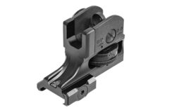
37. Forged Carry Handle
The AR-15 Forged Carry Handle is a key structural component of the carry handle rear sight assembly on a firearm, known for its enhanced strength and durability due to the forging process. This component serves dual purposes: as a physical handle for carrying the firearm and as an integrated part of the sighting system.
- Material: The handle is made through a forging process, which involves shaping metal under high pressure and temperature. This method significantly enhances its strength, durability, and resistance to wear, making it a reliable component for frequent use.
- Function: Beyond serving as a convenient handle for carrying the firearm, it also houses the rear sight assembly, playing a pivotal role in the firearm's aiming mechanism. The design ensures that the rear sight is securely mounted, providing a stable and consistent platform for accurate sighting.
- Role in Operation: The Forged Carry Handle is integral to the firearm's overall functionality, offering a robust structure that contributes to the steadiness and reliability of the sighting system. Its sturdy design aids in maintaining the alignment of the rear sight, essential for precise aiming and shooting.
- Maintenance: While the forged construction ensures longevity, regular maintenance is still necessary to keep the carry handle in optimal condition. This includes checking for any signs of wear or damage and ensuring that the rear sight remains securely attached and aligned.
The Forged Carry Handle's robust construction and dual functionality underscore its importance in enhancing the firearm's usability and reliability, especially concerning accurate sighting and ease of handling.
38. Rear Sight Elevation Spring Pin
The Rear Sight Elevation Spring Pin is an essential element within the rear sight assembly of a firearm, playing a pivotal role in anchoring the elevation spring. This pin is fundamental in preserving the correct positioning and functionality of the spring, which is crucial for the rear sight's elevation adjustment accuracy.
- Material: Crafted from durable materials, this pin is designed to withstand the forces exerted by the elevation spring and the operational stresses of the firearm, ensuring it maintains its structural integrity and function over time.
- Function: Its main purpose is to securely fasten the elevation spring in place, preventing any movement that could lead to inconsistency or loss of tension. This stability is vital for the precise adjustment and functioning of the rear sight's elevation mechanism.
- Role in Operation: The Elevation Spring Pin is crucial for the rear sight's accuracy and reliability. By securing the elevation spring, it ensures that the rear sight maintains its set elevation, allowing for consistent and reliable aim adjustments.
- Maintenance: Regular inspection and maintenance are necessary to ensure that the pin is not worn or damaged, which could affect the stability and effectiveness of the elevation spring and, consequently, the accuracy of the rear sight.
The Rear Sight Elevation Spring Pin's role is indispensable in the firearm's sighting mechanism, ensuring the elevation adjustments are stable and reliable, thus contributing significantly to the overall accuracy and dependability of the firearm.
39. Cross Bolt (2)
The Cross Bolts are essential elements in the assembly of a firearm, particularly in attaching the carry handle rear sight assembly to the firearm's upper receiver via the picatinny rail. These bolts are key in ensuring that the sight assembly is securely fastened and remains consistently stable during the operation of the firearm.
- Material: Constructed from robust materials, the Cross Bolts are designed to endure the stresses and vibrations of firing, maintaining their grip and preventing loosening over time to ensure long-lasting reliability.
- Function: The primary function of these bolts is to secure the carry handle rear sight assembly firmly to the picatinny rail, providing a stable platform for the sighting system. This firm attachment is crucial for preventing any movement or misalignment of the rear sight, which is essential for accurate aiming.
- Role in Operation: The Cross Bolts are vital for the stability and alignment of the rear sight assembly. Their ability to keep the assembly locked in place directly impacts the firearm's accuracy and the shooter's confidence in consistent aim and shot placement.
- Maintenance: Regular checks are necessary to ensure the Cross Bolts remain tight and secure. Any loosening could lead to a shift in the rear sight assembly, affecting the firearm's accuracy. Proper maintenance includes ensuring the bolts are not corroded, damaged, and are adequately torqued to the manufacturer's specifications.
The Cross Bolts' functionality and condition are critical for the overall performance and reliability of the firearm's sighting system, highlighting their importance in the precision and dependability of the shooter's aim.
40. Thumb Nut Assembly
The Thumb Nut Assembly, comprising two thumb nuts, plays a crucial role in the user-friendly attachment and detachment of the rear sight or handle assembly on a firearm. This assembly is specifically designed to enable the easy and efficient tightening or loosening of the cross bolts, facilitating the swift installation or removal of the sight/handle without the necessity for tools.
- Material: These thumb nuts are crafted from durable materials, ensuring they can withstand repeated use and provide reliable performance in securing the assembly to the firearm.
- Function: The main function of the thumb nut assembly is to provide a convenient and efficient means of adjusting the tightness of the cross bolts. This allows for quick and tool-free installation or removal of the rear sight/handle assembly, enhancing the firearm's adaptability in various situations.
- Role in Operation: The thumb nuts are instrumental in securing the rear sight/handle assembly firmly to the firearm, ensuring it remains stable and accurate during use. Their design allows for quick adjustments, enabling shooters to easily modify their firearm's configuration in response to different operational requirements or preferences.
- Maintenance: While the thumb nuts are designed for ease of use, regular checks are recommended to ensure they remain in good condition and function correctly. This includes ensuring they are not stripped, corroded, or damaged, which could affect their ability to secure the assembly effectively.
The Thumb Nut Assembly's contribution to the functionality and versatility of the firearm's sighting system underscores its importance, providing a secure yet easily adjustable mechanism that caters to the dynamic needs of the user.


41. Clamping bar
The Clamping Bar is an essential component in the rear sight/handle assembly of a firearm, acting as a key tension element that ensures the assembly's secure attachment to the firearm. This bar works in conjunction with thumb nuts and cross bolts to maintain a firm and stable connection to the Picatinny rail or other mounting systems.
- Material: Made from strong, durable materials, the clamping bar is designed to withstand significant pressure and maintain its structural integrity over time, ensuring reliable performance and longevity.
- Function: Its primary function is to apply consistent and even pressure at the connection point between the rear sight/handle assembly and the firearm's mounting rail. This pressure is crucial for preventing any movement or loosening that could compromise the sighting system's stability.
- Role in Operation: By ensuring that the rear sight/handle assembly remains securely fastened to the firearm, the clamping bar plays a critical role in the overall stability and accuracy of the sighting system. It prevents shifts or vibrations that could affect aim and shot precision.
- Maintenance: Regular inspection and maintenance are vital to ensure the clamping bar remains effective. This includes checking for signs of wear, ensuring it is not bent or damaged, and confirming that it applies even pressure to maintain the assembly's secure attachment.
The Clamping Bar's role is pivotal in maintaining the structural integrity and functional stability of the firearm's rear sight/handle assembly, underlining its importance in the effectiveness and reliability of the firearm's sighting system.
42. Forward Assist Spring Pin
The Forward Assist Spring Pin is an integral part of a firearm's forward assist mechanism, tasked with securing the forward assist plunger in its designated housing. This small but vital component plays a key role in ensuring the plunger's correct alignment and functionality, which is crucial for the effective operation of the forward assist system.
- Material: Constructed from durable materials, the spring pin is designed to endure the pressures and movements associated with the forward assist's operation, ensuring longevity and reliability.
- Function: Its primary role is to hold the forward assist plunger in place, ensuring it remains properly aligned within its housing. This alignment is crucial for the plunger's effective engagement with the firearm's bolt, allowing the forward assist mechanism to function as intended.
- Role in Operation: The Forward Assist Spring Pin is essential for the correct operation of the forward assist mechanism, which is used by shooters to manually ensure the bolt is fully closed and locked. This mechanism is particularly important for ensuring the firearm operates reliably, especially in situations where a round must be securely chambered.
- Maintenance: Regular maintenance is necessary to ensure the spring pin remains in optimal condition. This includes checking for signs of wear or damage and ensuring that the pin retains its structural integrity to continue providing reliable support for the forward assist plunger.
By securing the forward assist plunger effectively, the Forward Assist Spring Pin ensures the consistent functionality and reliability of the forward assist mechanism, underscoring its importance in the overall operation and safety of the firearm.
43. Forward Assist Plunger
The Forward Assist Plunger is an essential element of the forward assist mechanism on a firearm, allowing the user to manually ensure the bolt's complete engagement and lock-in. This component is crucial for the firearm's functionality, particularly in instances where the bolt has not fully seated.
- Material: Constructed from durable materials, the plunger is designed to withstand repeated use and apply consistent pressure to the bolt, ensuring its longevity and reliability in the firearm's operation.
- Function: Its main function is to be manually pressed or pushed by the user, which in turn engages the bolt and ensures it is fully seated and locked in place. This is especially vital in scenarios where the bolt has not fully closed, ensuring the firearm is ready and safe to fire.
- Role in Operation: The Forward Assist Plunger is the user-interactive part of the forward assist mechanism, enabling manual intervention to confirm the bolt's full engagement. This action is crucial for the firearm's reliable performance, ensuring it operates correctly and maintains readiness for use.
- Maintenance: Regular inspection and maintenance are essential to ensure the plunger functions effectively. It should be checked for wear, proper alignment, and smooth operation to guarantee that it can consistently apply the necessary pressure to the bolt.
By providing a means for manual intervention to ensure the bolt's full engagement, the Forward Assist Plunger plays a vital role in the firearm's operational reliability and safety, making it a key component in the forward assist mechanism.
44. Pawl Spring Pin
The Pawl Spring Pin is a vital element in the pawl assembly of a firearm's forward assist mechanism, ensuring the pawl's proper placement and functionality. This pin is crucial for the smooth and efficient operation of the forward assist, contributing significantly to the mechanism's overall reliability and effectiveness.
- Material: Made from high-strength materials, the Pawl Spring Pin is engineered to endure the mechanical stresses it encounters during the operation of the forward assist, ensuring its durability and sustained performance.
- Function: Its primary role is to maintain the correct positioning of the pawl within the forward assist assembly. This secure positioning is essential for the pawl's interaction with the bolt carrier, enabling the forward assist mechanism to function as intended, particularly in aiding the manual closure of the bolt.
- Role in Operation: The pin is integral to the forward assist's operation, allowing the pawl to engage effectively with the bolt carrier. This engagement is crucial for the manual actuation of the forward assist, ensuring that the bolt is fully seated and locked in place when necessary.
- Maintenance: Regular maintenance is vital to ensure the Pawl Spring Pin remains in optimal condition. This includes checking for wear or damage that could compromise the pawl's positioning or the forward assist's functionality, ensuring the firearm's readiness and operational safety.
The Pawl Spring Pin's role in maintaining the pawl's positioning and ensuring the effective operation of the forward assist mechanism underscores its importance in the firearm's functionality, highlighting the significance of each component in the overall reliability and safety of the weapon.
45. Pawl Spring
46. Pawl Detent
The Pawl Detent is a crucial component within the pawl assembly of the forward assist mechanism on a firearm, playing a key role in the precise and effective operation of the forward assist. It functions in conjunction with the pawl spring to ensure the pawl's proper engagement and functionality.
- Material: Constructed from high-quality materials, the Pawl Detent is designed to withstand the pressures and movements involved in the forward assist mechanism, ensuring durability and reliability throughout its use.
- Function: The primary function of the Pawl Detent is to provide a specific engagement point for the pawl, ensuring it aligns correctly with the other components of the forward assist mechanism. It helps maintain the pawl in the right position, enabling it to exert the necessary pressure for effective engagement and smooth disengagement.
- Role in Operation: The detent is vital for the pawl's operation, working with the spring to provide the tension and positioning needed for the pawl to function correctly. This ensures that the forward assist can reliably help seat the bolt fully into the chamber, a critical aspect of the firearm's operation, especially in scenarios where manual assistance is required to ensure the bolt's complete engagement.
- Maintenance: Regular maintenance is essential to ensure the Pawl Detent continues to function effectively. This includes checking for wear, ensuring it is not damaged or out of position, and confirming that it provides the correct tension and alignment for the pawl's operation.
The interaction between the Pawl Detent and the pawl spring is fundamental to the forward assist mechanism's efficiency, underscoring the importance of each component in the reliable operation of the firearm's forward assist, contributing to the firearm's overall functionality and user's safety.
47. Forward Assist Pawl
The pawl is a spring-loaded component in the forward assist mechanism of a firearm, specifically designed to engage with the teeth on the side of the Bolt Carrier Group (BCG). This engagement allows the user to manually ensure the bolt is fully seated in the event of a partial or incomplete closure.
- Material: Constructed from durable materials, the pawl is built to exert the necessary pressure and engage firmly with the BCG, ensuring longevity and reliability in its function.
- Function: The primary purpose of the pawl is to interact with the BCG's teeth, enabling the shooter to manually advance the bolt into its fully seated position, ensuring the firearm is properly chambered and ready to fire.
- Role in Operation: In situations where the bolt does not fully close on its own, the pawl, activated by the forward assist mechanism, provides the necessary pressure to secure the bolt in place, aiding in the firearm's correct operation.
- Maintenance and Safety: Regular inspection and maintenance are crucial to ensure the pawl functions as intended. It's important to note that if the bolt does not close properly, forcing it with the pawl should only be considered in critical situations. In normal circumstances, a malfunctioning bolt indicates the need for inspection and repair by a qualified gunsmith to prevent potential malfunctions or hazards.
The pawl's function is integral to the forward assist mechanism, providing an essential manual override that ensures the firearm's bolt is fully engaged, contributing to the safe and reliable operation of the firearm in critical situations.
48. Forward Assist Spring Pin
The Forward Assist Spring Pin is an essential part of the forward assist assembly in a firearm, playing a key role in the mechanism's ability to function correctly. This component ensures the appropriate tension is applied within the assembly, crucial for the mechanism's proper operation and interaction with the firearm's bolt carrier group (BCG).
- Material: Made from resilient materials, the Forward Assist Spring Pin is engineered to provide consistent tension and withstand the rigors of repeated use, ensuring it maintains its effectiveness over time.
- Function: Its main function is to exert pressure within the forward assist assembly, specifically influencing the pawl's position. This ensures that the pawl is retracted and remains clear of the BCG during the firearm's regular operation, preventing any unintended engagement.
- Role in Operation: The spring pin is critical for the forward assist mechanism, allowing the user to manually ensure the bolt's full engagement when necessary. Simultaneously, it ensures that the forward assist's components, particularly the pawl, are retracted and do not interfere with the BCG during normal operation, thus safeguarding against undue wear or operational hindrances.
- Maintenance: Regular inspection and maintenance are vital to ensure that the Forward Assist Spring Pin functions optimally. This includes checking for signs of wear or fatigue and ensuring that it continues to provide the necessary tension for the forward assist assembly to operate effectively.
By maintaining the correct tension and functionality within the forward assist assembly, the Forward Assist Spring Pin is indispensable for the mechanism's reliability, ensuring it is available to aid the firearm's operation when required while avoiding interference during standard cycling processes.
49. Upper Receiver
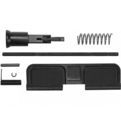
50. Ejection Port Cover Pin
The Ejection Port Cover Pin is an integral component of a firearm, specifically designed to secure the ejection port cover to the upper receiver. This pin not only ensures that the cover remains in place but also acts as a pivotal hinge, allowing the cover to rotate.
- Material: The pin is crafted from robust materials to endure the mechanical actions and environmental stress it encounters during the operation of the firearm.
- Function: Its primary function is to provide a secure attachment point for the ejection port cover, enabling it to pivot open or closed. When the firearm discharges, this pin allows the cover to open, facilitating the ejection of spent casings. Conversely, when the firearm is idle, the cover can be shut to shield the internal mechanisms from contaminants like dirt and debris.
- Role in Operation: The Ejection Port Cover Pin is crucial for the smooth operation and alignment of the ejection port cover with the upper receiver. This alignment ensures that the cover operates without hindrance, maintaining the firearm's functionality and protecting its internal parts.
- Maintenance: Regular inspection and maintenance of the Ejection Port Cover Pin are essential to preserve its functionality and the overall integrity of the firearm. This includes checking for signs of wear or damage and ensuring that the pin and cover operate smoothly.
The Ejection Port Cover Pin plays a vital role in the firearm's mechanism, particularly in the operation and maintenance of the ejection port cover, underscoring its importance in the firearm's performance and reliability.


51. Ring, Retaining Cover
The Retaining Ring, often referred to as the Ring, Retaining Cover, is a small but essential component designed to secure the Ejection Port Cover Pin within the firearm. It ensures that the pin remains firmly in place, preventing it from dislodging during the operation of the firearm.
- Material: Crafted from durable materials, the retaining ring is engineered to withstand the dynamic forces it encounters during the firearm's operation, maintaining its integrity and function over time.
- Function: The primary role of the Retaining Ring is to anchor the Ejection Port Cover Pin, ensuring it stays attached to the upper receiver. This is vital for the stability and functionality of the ejection port cover, as the pin is the component around which the cover pivots.
- Role in Operation: By securing the Ejection Port Cover Pin, the retaining ring indirectly contributes to the reliable operation of the ejection port cover. It ensures that the pin does not dislodge, allowing the cover to function correctly—opening to eject spent casings and closing to protect the firearm's internal components.
- Maintenance: Regular checks are essential to ensure that the Retaining Ring is not worn or damaged, which could compromise the pin's security. Proper maintenance ensures the longevity and reliable operation of this component and, by extension, the ejection port cover mechanism.
The Retaining Ring plays a pivotal role in maintaining the structural integrity and operational reliability of the firearm's ejection port cover system, highlighting its significance in the overall functionality of the weapon.
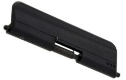
52. Ejection Port Cover Spring
The Ejection Port Cover Spring is a crucial component in the functionality of a firearm's ejection port cover. It provides the necessary tension and force to swiftly open the cover and maintains it in an open position, ensuring that it does not rattle, shake, or close accidentally during firearm operation.
- Material: Made from high-grade spring steel, the Ejection Port Cover Spring is designed for resilience and durability, ensuring it maintains its tension and structural integrity even under repeated use.
- Function: The spring's primary function is to facilitate the rapid opening of the ejection port cover when the firearm is discharged. It exerts a force that propels the cover open, allowing spent casings to be ejected without obstruction. Additionally, it holds the cover in the open position, preventing unwanted closure that could interfere with the firearm's operation or cause noise through rattling.
- Role in Operation: The Ejection Port Cover Spring is vital for the seamless performance of the ejection port cover. It ensures that the cover operates efficiently, opening promptly when required and remaining open during firing, thus contributing to the overall reliability and functionality of the firearm.
- Maintenance: Regular inspection and maintenance of the Ejection Port Cover Spring are essential to ensure its effectiveness and durability. This includes checking for signs of wear, loss of tension, or damage, as a compromised spring could affect the operation of the ejection port cover.
The Ejection Port Cover Spring is integral to the proper functioning of the ejection port cover, playing a key role in the firearm's operational reliability by ensuring the cover opens swiftly and remains stable during use.
53. Ejection Port Cover
The Ejection Port Cover is the small door that keeps the ejection port clean by preventing debris from entering when it is closed.
- Material: Typically made from durable metals, the Ejection Port Cover is designed to withstand the harsh conditions typical of firearm use, ensuring it remains functional over time.
- Function: The cover's main purpose is to protect the ejection port from dust, dirt, and other environmental contaminants when the firearm is not in use. This prevents blockages and maintains the cleanliness and functionality of the critical internal mechanisms.
- Role in Operation: The Ejection Port Cover is crucial for maintaining the reliability of the firearm. By shielding the ejection port from contaminants, it ensures that the firearm operates smoothly and without malfunction caused by debris entering the ejection port.
- Maintenance: Regular checks and cleaning of the Ejection Port Cover are essential to ensure it performs its protective role effectively. Keeping the cover clean and free from debris helps in preserving its condition and functionality.
The Ejection Port Cover is a fundamental component of the firearm, essential for operational reliability by protecting the ejection port from debris, thereby ensuring the firearm remains clean and ready for use.
54. Handguard Snap Ring
55. Weld Spring
The Weld Spring is a crucial component in a firearm's handguard assembly, designed to provide necessary tension for the handguard.
- Material: Typically made from high-quality spring steel, the Weld Spring is engineered to sustain consistent tension and resist fatigue over extended periods of use.
- Function: The primary role of the Weld Spring is to exert constant pressure on the handguard, ensuring it remains securely attached to the firearm and stable during use. This tension is vital for maintaining the handguard’s position and preventing rattling or shifting that could impact performance.
- Role in Operation: The Weld Spring is instrumental in the stability and operational integrity of the firearm's handguard. By maintaining appropriate tension, it ensures that the handguard provides a reliable and steady grip surface, which is essential for accurate shooting.
- Maintenance: Regular inspection of the Weld Spring for wear or loss of tension is essential. A spring that shows signs of fatigue should be replaced to maintain the handguard’s stability and the overall safety and functionality of the firearm.
The Weld Spring is an essential element in the assembly of the firearm’s handguard, providing the necessary tension to keep the handguard securely in place and enhancing the firearm's reliability and accuracy.
56. Delta Ring
The Delta Ring is a critical component of the firearm's handguard assembly, designed to provide the necessary tension to secure the handguard in place around the barrel.
- Material: Usually made from durable steel, the Delta Ring is built to endure the physical stresses and heat associated with firearm operation.
- Function: The primary role of the Delta Ring is to provide a secure mounting platform for the handguard, using tension to clamp it against the upper receiver. This ensures the handguard remains stable and secure during the firing process.
- Role in Operation: Essential for the effective attachment of the handguard, the Delta Ring facilitates quick and secure handguard installation or removal. It plays a key role in maintaining the structural integrity of the firearm, supporting accurate and safe operation.
- Maintenance: Regular maintenance of the Delta Ring involves ensuring it functions smoothly and retains its tension. Inspecting for signs of wear or damage and ensuring it operates freely without binding are critical to maintaining the firearm’s functionality and safety.
The Delta Ring is vital for securely attaching the handguard, enhancing the firearm's overall reliability and ease of use by ensuring the handguard remains firmly in place during operation.
57. Carbine Gas Tube
The Carbine AR-15 Gas Tube is a critical component in a firearm, specifically designed to transport a portion of the gas released upon firing from the gas block to the bolt key on the Bolt Carrier Group (BCG). It is typically located underneath the handguard.
- Material: Constructed from heat-resistant materials like stainless steel, the Carbine Gas Tube is built to withstand high temperatures and pressures from the gas expelled during firing.
- Function: This gas tube plays a vital role in the firearm's cycling process by directing gas into the BCG, facilitating the recoil operation that ejects the spent casing and chambers a new round.
- Role in Operation: Essential for the semi-automatic operation of the firearm, the Carbine Gas Tube ensures that the rifle cycles correctly and reliably. Its proper function is crucial for maintaining the firearm's overall performance and rate of fire.
- Maintenance: Regular maintenance and inspection of the Carbine Gas Tube are necessary to prevent blockages and ensure it is free from damage. Any disruption in the gas flow can affect the firearm's operation, making cleanliness and integrity key to its functionality.
The Carbine Gas Tube is fundamental in leveraging the gas from a fired round to support the semi-automatic action of the firearm, ensuring consistent operation and enhancing the shooter's ability to maintain rapid fire.
58. Barrel Indexing Pin
The Barrel Indexing Pin is a small but crucial component located on the top of the barrel of a firearm. It is designed to index and maintain the barrel in an upright position during installation and use.
- Material: Typically made from durable metal, the Barrel Indexing Pin is engineered to withstand the mechanical stresses of firearm assembly and operation without deforming.
- Function: This pin's primary function is to ensure proper alignment of the barrel within the firearm's assembly. By securing the barrel in the correct orientation, it facilitates accurate installation and optimal performance.
- Role in Operation: The Barrel Indexing Pin is essential for the firearm's accuracy and overall function. It helps maintain the barrel's alignment during firing, preventing any shift that could affect the bullet's trajectory.
- Maintenance: Regular checks for the Barrel Indexing Pin's integrity are important. Ensuring it is not bent or loose is crucial for maintaining the firearm's accuracy and safety.
The Barrel Indexing Pin is a key element in maintaining the structural alignment of the barrel, crucial for ensuring that the firearm operates reliably and shoots accurately.
59. Barrel Extension
The AR-15 Barrel Extension is an integral part of the firearm's barrel that recesses into the upper receiver. It is designed to fit snugly into place, ensuring a secure connection between the barrel and the receiver.
- Material: Typically made from the same high-strength steel as the barrel, the Barrel Extension is built to endure the mechanical and thermal stresses of firing.
- Function: This component is critical for aligning the barrel precisely within the upper receiver. It provides the necessary stability and ensures that the barrel assembly remains securely attached, enhancing the firearm's overall accuracy and reliability.
- Role in Operation: The Barrel Extension plays a vital role in the structural integrity of the firearm. By securing a tight fit within the upper receiver, it supports proper alignment and seamless operation during firing.
- Maintenance: Installation of the Barrel Extension may require the expertise of a gunsmith, particularly to apply the proper copper Aeroshell anti-seize for a durable and heat-resistant fit. Regular checks to ensure that it remains securely fastened and properly aligned are essential for maintaining performance.
The Barrel Extension is a fundamental component that contributes significantly to the precision and operational reliability of the firearm, making it essential for achieving consistent accuracy and safe handling.
60. Thermoset Handguard
The Thermoset AR-15 Handguard is a two-piece handguard made from thermoset materials, designed to give a firearm a retro look and feel. Unlike the more modern free-floating handguards, this style attaches directly to the barrel, influencing the traditional handling characteristics of the firearm.
- Material: Crafted from durable thermoset plastics, this handguard is designed to resist heat and mechanical stress, maintaining its integrity and aesthetic under typical shooting conditions.
- Function: This handguard provides a stable, non-floating platform for handling the firearm. It covers the barrel, offering protection from heat and providing a comfortable grip for the shooter.
- Role in Operation: While it does not offer the same accuracy enhancements as a free-floating handguard, the Thermoset Handguard is integral for maintaining the classic appearance and feel of historical or retro-style firearms. It also contributes to safer firearm handling by shielding the shooter from the hot barrel.
- Maintenance: Maintenance of the Thermoset Handguard involves regular cleaning and checks for cracks or wear, especially after extensive use, to ensure it continues to provide adequate protection and maintains its appearance.
The Thermoset Handguard is a key component for firearm enthusiasts who prefer a vintage style, adding to the firearm's aesthetic appeal while fulfilling essential protective and ergonomic functions.
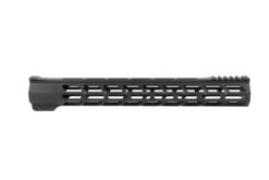
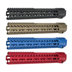

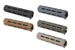
61. Handguard Cap
62. Front Sight Post
63. Front Sight Detent
The Front Sight Detent is a small but crucial component designed to maintain tension on the Front Sight Post, ensuring it remains fixed in position during use.
- Material: Typically made from high-strength steel, the Front Sight Detent is durable enough to endure the forces exerted during regular firearm operation.
- Function: Its primary role is to apply consistent pressure to the Front Sight Post, preventing any unwanted movement or shifting that could impact the firearm's accuracy.
- Role in Operation: The Front Sight Detent is vital for the reliability of the firearm's sighting system. By securing the Front Sight Post in its proper position, it helps maintain consistent accuracy, which is essential for effective shooting.
- Maintenance: Regular checks are recommended to ensure the Front Sight Detent is not worn or damaged, which could compromise its ability to hold the Front Sight Post securely. Replacing the detent may be necessary if it no longer provides adequate tension.
The Front Sight Detent is essential for keeping the Front Sight Post stable and accurate, thereby enhancing the overall performance and reliability of the firearm’s sighting system.
64. Front Sight Detent Spring
The Front Sight Detent Spring is a critical component in the firearm's front sight assembly, designed to exert the necessary tension on the Front Sight Detent, keeping it in place.
- Material: This spring is usually made from high-quality spring steel, chosen for its ability to maintain elasticity and strength over repeated use and under varying environmental conditions.
- Function: The main function of the Front Sight Detent Spring is to provide consistent pressure on the Front Sight Detent, ensuring it effectively secures the Front Sight Post against any movement or vibration that could affect shooting accuracy.
- Role in Operation: The Front Sight Detent Spring is essential for the stability and reliability of the firearm’s front sight. It plays a crucial role in maintaining the proper alignment of the sighting system, which is vital for accurate targeting.
- Maintenance: Regular inspection and maintenance are necessary to ensure the spring does not become compressed or lose its tension over time. Replacing the spring may be required if it shows signs of wear or fatigue to maintain optimal function.
The Front Sight Detent Spring is indispensable in supporting the precise operation of the firearm's front sight system, contributing significantly to the consistent accuracy and reliability of the firearm.
65. Gas Tube Roll Pin
The Gas Tube Roll Pin is a small yet crucial component used to secure the gas tube in its designated place within a firearm.
- Material: Made from hardened steel, this roll pin is engineered to endure the stress and heat of firing, ensuring durability and reliability.
- Function: Its primary function is to fasten the gas tube firmly to the gas block, preventing any movement that could disrupt the firearm's operation. The roll pin fits snugly within pre-drilled holes, locking the gas tube in position.
- Role in Operation: The Gas Tube Roll Pin is vital for the proper functioning of the firearm's gas-operated system. By securing the gas tube, it ensures the correct routing of gases from the barrel back to the action, which is essential for the cycling process in semi-automatic firearms.
- Maintenance: Regular inspection is recommended to ensure the Gas Tube Roll Pin is not loosened or damaged, as this could lead to operational failures. Replacement may be necessary if the pin shows signs of wear or corrosion.
The Gas Tube Roll Pin is essential for maintaining the structural integrity and operational reliability of the firearm’s gas system, playing a key role in ensuring the seamless function of gas-operated firearms.
66. Front Sight Base with Bayonet Lug
The Front Sight Base with Bayonet Lug is a multifunctional component on a firearm that serves as both the gas block and the front sight. This particular model includes a bayonet lug attachment for added functionality.
- Material: Typically made from durable, heat-resistant metal, this front sight base is built to withstand the pressures and temperatures associated with firing, as well as the physical demands of mounting a bayonet.
- Function: The primary role of this component is to channel gases from the barrel to operate the firearm's cycling mechanism while also providing a stable platform for the front sight, aiding in accurate shooting. The addition of the bayonet lug allows for the attachment of a bayonet, enhancing the firearm's utility in close combat situations.
- Role in Operation: As a critical part of the firearm's gas system and sighting arrangement, the Front Sight Base with Bayonet Lug ensures proper gas flow for reliable operation and stable, accurate sighting for effective targeting. The bayonet lug offers the practicality of a melee attachment when needed.
- Maintenance: Regular inspection and cleaning of the Front Sight Base with Bayonet Lug are necessary to ensure it remains free of debris and corrosion, which could impact gas flow or sight accuracy. The bayonet lug should also be checked for integrity and proper attachment capability.
The Front Sight Base with Bayonet Lug is essential for the dual functionality of directing gas operation and providing sighting assistance, while the bayonet lug adds a significant tactical advantage to the firearm.
67. Barrel Subassembly
The Barrel Subassembly is a comprehensive unit that includes the barrel itself, complete with essential components like the barrel indexing pin, pre-drilled holes, internal rifling, and external threading.
- Material: Typically constructed from high-grade steel, the barrel subassembly is designed to withstand the intense pressures and heat generated by fired rounds, ensuring durability and longevity.
- Function: The barrel indexing pin ensures correct alignment during installation, helping maintain the barrel's upright position. Pre-drilled holes accommodate various attachments and components, while the rifling inside the barrel is crucial for stabilizing the bullet by imparting a spin, enhancing accuracy over distance. Threading on the barrel allows for the addition of accessories like muzzle devices.
- Role in Operation: The Barrel Subassembly is fundamental to the firearm's overall performance. Its precise construction affects everything from the ease of assembly to the accuracy and reliability of the firearm. The rifling is particularly vital for the ballistic performance of the bullets fired.
- Maintenance: Regular maintenance of the Barrel Subassembly involves cleaning the barrel to prevent buildup and checking for wear or damage. Proper care of the rifling and threading is essential to ensure continued accuracy and functionality.
The Barrel Subassembly is crucial, serving as the backbone of the firearm’s operational structure, directly influencing its accuracy, reliability, and versatility in customization.
68. Front Sight Taper Pins
Front Sight Taper Pins are precision-engineered pins used to securely affix the front sight base to a firearm's barrel, ensuring proper alignment and stability.
- Material: These pins are typically machined from high-quality steel or stainless steel to provide strength and durability. They can be available in both coated and uncoated finishes, with coatings enhancing corrosion resistance and durability.
- Function: The taper design of these pins allows for a more secure fit as they are driven into place, matching the taper of corresponding holes in the front sight base and barrel. This design ensures a tight, secure mounting that resists loosening under the stress of firing.
- Role in Operation: Front Sight Taper Pins play a crucial role in the firearm's accuracy and reliability. By securely attaching the front sight base to the barrel, they help maintain consistent sight alignment, which is essential for accurate shooting.
- Maintenance: Regular inspection is recommended to ensure the pins are not loosened or showing signs of wear. If removal is necessary, care must be taken to avoid damaging the pins or barrel, which might affect the firearm's accuracy.
Front Sight Taper Pins are essential for a stable and reliable sighting system, contributing significantly to the overall effectiveness and accuracy of the firearm.
69. Barrel Nut
The Barrel Nut is a crucial component used to securely attach the barrel to the upper receiver of a firearm. It ensures the barrel is properly aligned and firmly installed.
- Material: Typically made from strong, durable metal capable of withstanding the substantial forces exerted during firearm operation.
- Function: The Barrel Nut's primary role is to lock the barrel in place, providing a stable platform for accurate and reliable shooting. It is designed to fit around the barrel extension and screw into the upper receiver, ensuring a tight connection.
- Role in Operation: Proper installation of the Barrel Nut is critical to the firearm's performance. It must be torqued to specific manufacturer specifications to ensure optimal alignment and security, which directly impacts the firearm's accuracy and safety.
- Maintenance: Regular checks are recommended to ensure the Barrel Nut remains properly torqued and free from wear or damage. Any loosening can affect the firearm’s performance, so adherence to maintenance guidelines is crucial.
The Barrel Nut is essential for maintaining the structural integrity and operational reliability of the firearm, playing a key role in ensuring the barrel remains securely attached to the upper receiver.

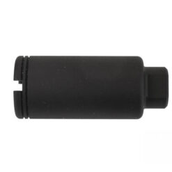
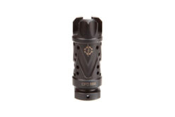
70. Front Sling Swivel Rivet
71. Front Sling Swivel
The Front Sling Swivel is the primary attachment point for a sling on the front end of a firearm, designed to enhance mobility and handling.
- Material: Typically crafted from durable metal, the Front Sling Swivel is built to withstand the physical demands of active use and the environmental factors associated with various shooting conditions.
- Function: This component serves as the pivotal connection point for a sling, allowing the firearm to be carried securely and accessed quickly. It enables the sling to rotate slightly, providing flexibility and ease of movement for the user.
- Role in Operation: The Front Sling Swivel is essential for the effective use of a sling, facilitating easier transport and maneuverability of the firearm. It helps distribute the weight of the gun, reducing fatigue during prolonged use and improving the shooter's readiness and stability.
- Maintenance: Regular maintenance includes checking the swivel for secure attachment and ensuring it rotates freely without excessive play. It should also be inspected for signs of wear or corrosion, which could impair its functionality.
The Front Sling Swivel is crucial for adding carrying capability to a firearm, significantly enhancing the user's comfort and operational efficiency, especially during extended periods of handling or movement.
72. Crush Washer
73. Flash Suppressor
The Flash Suppressor is a AR-15 muzzle device designed to minimize the visible flash produced when a round is fired from a firearm. This device helps conceal the shooter's position and reduces the blinding effect of the flash on the shooter in low-light conditions.
- Material: Typically constructed from high-strength steel or other durable metals, flash suppressors are built to withstand the intense heat and pressure that results from firing a weapon.
- Function: The main function of a Flash Suppressor is to disperse the burning gases that exit the muzzle when a firearm is discharged. This dispersion reduces the size and brightness of the muzzle flash, making it less visible.
- Role in Operation: A Flash Suppressor is crucial for tactical applications where concealment is necessary. It also plays a role in enhancing the shooter’s vision during low-light or night-time operations by minimizing disruptive muzzle flash.
- Maintenance: Regular cleaning and inspection of the Flash Suppressor are important to prevent carbon build-up and ensure it remains functional. Proper installation is critical to ensure that it works effectively and does not affect the firearm's accuracy.
- Alternatives: While a Flash Suppressor is specifically designed to reduce muzzle flash, other muzzle devices like flash hiders, muzzle brakes, and sound suppressors can also be used depending on the desired effect. Each has distinct characteristics affecting recoil, sound suppression, and flash reduction.
The Flash Suppressor is an essential component for improving a firearm's tactical effectiveness by reducing muzzle flash, thereby helping to maintain the shooter's concealment and vision in adverse conditions.
74. Buffer Spring
The Buffer Spring is a critical component within the recoil management system of a firearm, specifically designed to return the Bolt Carrier Group (BCG) to its ready position after each shot.
- Material: Typically made from high-grade spring steel, the Buffer Spring is engineered to endure the compressive forces and cycling stresses involved in the firearm's operation.
- Function: The main function of the Buffer Spring is to provide the necessary force to push the BCG back into position following recoil. This action is essential for cycling the firearm, as it allows for the ejection of the spent cartridge and the chambering of a new round.
- Role in Operation: The Buffer Spring is crucial for the reliable and smooth operation of the firearm. It ensures that the BCG returns to its ready position quickly and efficiently, facilitating continuous firing and enhancing the overall performance of the firearm.
- Maintenance: Regular maintenance of the Buffer Spring includes checking for signs of wear, loss of tension, or deformation. A worn or damaged Buffer Spring can lead to operational failures, so it may need to be replaced periodically to maintain optimal functionality.
The Buffer Spring plays an essential role in the firearm's recoil management system, contributing significantly to the reliability, speed, and overall readiness of the firearm during use.
75. Buffer Assembly
The AR-15 Buffer Assembly is a key component of a firearm's recoil management system, designed to absorb recoil and facilitate smooth operation. This assembly consists of a weighted buffer that contributes to the inertia needed for the cycling process.
- Material: Typically constructed from steel and other heavy metals, the weights within the buffer are chosen for their ability to provide sufficient inertia while maintaining durability.
- Function: The primary function of the Buffer Assembly is to slow down and absorb the rearward motion of the Bolt Carrier Group (BCG) after a round is fired. This buffering action helps to reduce felt recoil and prevent excessive wear on the firearm.
- Role in Operation: The Buffer Assembly plays a critical role in the cycling process by ensuring that the BCG moves back into position reliably and smoothly. Different weights are available for the Buffer Assembly to accommodate various types of ammunition and rates of fire, allowing customization for specific needs and preferences.
- Maintenance: Regular maintenance of the Buffer Assembly includes checking for signs of wear and ensuring that all components are functioning properly. The buffer weights should be inspected for damage or displacement, and the assembly may need to be adjusted or replaced to match the specific operational requirements of the firearm.
The Buffer Assembly is crucial for controlling recoil and enhancing the overall stability and performance of the firearm, making it an essential component for ensuring reliable action and comfortable handling.
76. Pin, Buttstock Slide Lock
The Pin, Buttstock Slide Lock is an essential component used to secure the buttstock at a desired position along the buffer tube of a firearm.
- Material: This pin is typically made from hardened steel, ensuring durability and resistance to wear, which is crucial given the stress and frequent adjustments it may undergo.
- Function: The primary function of the Buttstock Slide Lock Pin is to engage with specific holes in the buffer tube, allowing the buttstock to be locked into various positions. This adjustability helps accommodate different shooter preferences and body sizes, enhancing comfort and ergonomic use.
- Role in Operation: The Pin, Buttstock Slide Lock plays a critical role in the customization and functionality of the firearm's stock. By securely holding the buttstock in place, it ensures stability and accuracy while shooting.
- Maintenance: Regular inspection is necessary to ensure the pin is not bent, worn, or damaged, as any compromise in its integrity could affect the stability of the buttstock. Replacing the pin may be required if it shows signs of excessive wear or fails to hold the stock securely.
The Buttstock Slide Lock Pin is vital for maintaining the adjustability and secure positioning of the buttstock, contributing significantly to the ergonomic handling and overall performance of the firearm.
77. Lock Pin Spring
78. Telescoping Buttstock
The Telescoping AR-15 Buttstock is a versatile, adjustable stock designed for firearms, constructed to meet military specifications (mil-spec). It offers variable length settings to accommodate different shooter sizes and shooting styles.
- Material: This buttstock is primarily made from high-strength polymer, which provides durability and lightweight handling without sacrificing structural integrity.
- Function: The primary function of the Telescoping Buttstock is to allow for rapid and easy adjustment of the stock's length. This adjustability helps shooters achieve a comfortable and ergonomic fit, enhancing stability and control over the firearm during use.
- Role in Operation: The Telescoping Buttstock is essential for customizing the firearm's fit to the user, which can significantly impact shooting accuracy and comfort. It is designed to telescope in and out smoothly, locking securely at various points along the buffer tube to suit different body types and arm lengths.
- Maintenance: Maintenance involves regular cleaning to remove dirt and debris from the adjustment tracks and checking the mechanism for smooth operation. It’s also important to inspect the locking system for wear or damage to ensure that the stock remains securely in place when adjusted.
The Telescoping Buttstock is crucial for providing operational flexibility and personalized comfort, making it a popular choice for both military and civilian use due to its robustness and adjustability.
79. Telescoping Latch
The Telescoping Latch is a critical component of adjustable buttstocks, designed to allow the stock to be securely locked into any of the six positions machined into the buffer tube.
- Material: Typically made from durable metal, this latch is built to withstand frequent use and the physical stresses associated with the adjustment and locking of the buttstock.
- Function: The primary function of the Telescoping Latch is to engage with the corresponding positions on the buffer tube, allowing the user to adjust the length of the buttstock. By depressing the latch, the user can slide the buttstock forward or backward to select the most comfortable and effective position.
- Role in Operation: The Telescoping Latch is essential for the customization and ergonomic adjustment of the firearm. It ensures that the buttstock can be quickly and easily moved to suit the shooter's preference and then securely locked in place to maintain stability and accuracy during firing.
- Maintenance: Regular inspection and maintenance are necessary to ensure the latch operates smoothly and effectively. This includes checking for wear, ensuring it engages properly with the buffer tube positions, and verifying that it does not loosen or fail during operation.
The Telescoping Latch plays a crucial role in the functionality and adaptability of telescoping buttstocks, enhancing the firearm's overall usability and performance by allowing for quick and secure stock adjustments.
80. Lockpin Nut
The lockpin nut serves as a crucial component for securing the telescoping latch in position, ensuring its stability and functionality within adjustable buttstocks.
- Material: Constructed from durable metal, the lockpin nut is engineered to withstand the frequent manipulation and physical stresses associated with the operation of telescoping buttstocks.
- Function: Its primary function revolves around firmly holding the telescoping latch in place, allowing for smooth and reliable adjustments of the buttstock. This ensures the user can easily modify the length of the buttstock to their preferred position.
- Role in Operation: Essential for the seamless customization and ergonomic adaptability of the firearm, the lockpin nut plays a pivotal role in maintaining the stability and accuracy of the buttstock during firing. By securely locking the telescoping latch, it enables users to confidently engage with the firearm.
- Maintenance: Regular inspection and maintenance of the lockpin nut are essential to guarantee its proper functionality. This involves checking for any signs of wear, ensuring a secure fit with the telescoping latch, and addressing any issues that may arise during operation.
By securing the telescoping latch in place, the lockpin nut ensures the reliable performance of adjustable buttstocks, enhancing the overall usability and effectiveness of the firearm.
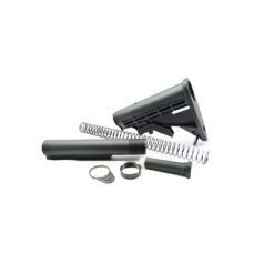
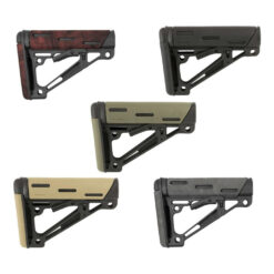
81. Roll Pin
This small but vital component plays a crucial role in securing the lockpin nut in position, ensuring its stability within the adjustable buttstock mechanism.
- Material: Crafted from durable metal, the roll pin is engineered to provide reliable support and endurance, effectively holding the lockpin nut in place during firearm operation.
- Function: The primary function of the roll pin is to firmly secure the lockpin nut, thereby preventing any unintended movement or dislodgement during adjustments to the buttstock.
- Role in Operation: Essential for the smooth functioning of the adjustable buttstock, the roll pin ensures the lockpin nut remains securely fastened, enabling users to confidently engage with the firearm.
- Maintenance: Regular inspection and maintenance of the roll pin are essential to ensure its continued effectiveness. This includes checking for signs of wear or damage and promptly replacing the roll pin if necessary to maintain optimal performance.
By securely holding the lockpin nut in place, the roll pin contributes to the overall stability and reliability of the adjustable buttstock, enhancing the firearm's usability and performance.
82. Buffer Tube, 6 Position Receiver Extension
This essential component serves as the housing for the buffer spring and buffer assembly within the firearm.
- Material: Typically constructed from durable metal, such as aluminum or steel, the buffer tube is designed to withstand the recoil forces generated during firing.
- Function: The primary function of the buffer tube is to provide a secure housing for the buffer spring and buffer assembly, facilitating the absorption and management of recoil energy.
- Variants: Buffer tubes can come in mil-spec or commercial grades, with slight differences in diameter. Mil-spec buffer tubes, like this one, adhere to military specifications for compatibility with a wide range of accessories and components.
- Compatibility: While mil-spec buffer tubes are standardized, commercial-grade buffer tubes may vary slightly in diameter, requiring compatible accessories for proper fitment.
- Role in Operation: Integral to the firearm's functionality, the buffer tube ensures smooth cycling of the action by controlling the movement of the buffer spring and buffer assembly during firing and cycling.
- Maintenance: Regular inspection and maintenance of the buffer tube are important to ensure its structural integrity and proper functionality. This includes checking for signs of wear, corrosion, or damage, and addressing any issues promptly to maintain optimal performance.
By housing the buffer spring and buffer assembly, the buffer tube plays a critical role in the firearm's operation, contributing to its reliability, stability, and overall performance.
83. Receiver Extension Nut
This essential component serves to secure the receiver extension, commonly known as the buffer tube, in place within the firearm's assembly.
- Material: Typically crafted from durable metal, such as steel or aluminum, the receiver extension nut is designed to withstand the forces exerted during firearm operation.
- Function: The primary function of the receiver extension nut is to firmly hold the receiver extension, or buffer tube, in its designated position within the firearm's receiver.
- Role in Operation: Integral to the stability and functionality of the firearm, the receiver extension nut ensures that the buffer tube remains securely attached, facilitating the proper cycling of the action during firing.
- Installation: Proper installation of the receiver extension nut is crucial for ensuring the stability and reliability of the firearm. It must be securely tightened to prevent any movement or loosening during operation.
- Maintenance: Regular inspection and maintenance of the receiver extension nut are important to ensure its continued effectiveness. This includes checking for signs of wear, corrosion, or damage, and addressing any issues promptly to maintain optimal performance.
By securely holding the receiver extension in place, the receiver extension nut plays a critical role in the overall stability and functionality of the firearm, contributing to its reliability and performance.
84. Collar, Buttstock Tube Lock
This component serves the crucial role of securely holding the AR-15 buffer tube in place, preventing any rotation or movement within the firearm's assembly.
- Material: Typically crafted from durable metal, such as steel or aluminum, the collar ensures reliable and stable positioning of the buffer tube.
- Function: The primary function of the collar, buttstock tube lock is to provide a secure locking mechanism for the buffer tube, preventing it from spinning or turning during firearm operation.
- Role in Operation: Essential to maintaining the stability and functionality of the firearm, the collar ensures that the buffer tube remains firmly fixed in its designated position within the receiver.
- Installation: Proper installation of the collar is essential for ensuring its effectiveness. It must be securely tightened to create a stable connection between the buffer tube and the firearm's receiver.
- Maintenance: Regular inspection and maintenance of the collar are necessary to ensure its continued reliability. This includes checking for signs of wear, corrosion, or damage, and addressing any issues promptly to maintain optimal performance.
By securely locking the buffer tube in place, the collar, buttstock tube lock enhances the overall stability and reliability of the firearm, contributing to its consistent performance during use.
85. Hammer with J Pin
This component serves as the mechanism that strikes the firing pin when the trigger is pulled, initiating the firing sequence within the firearm.
- Material: Typically crafted from durable steel, the hammer with J pin is designed to withstand repeated impacts and ensure reliable ignition of the cartridge.
- Function: The primary function of the hammer with J pin is to transfer energy from the trigger mechanism to the firing pin, causing it to strike the primer of the cartridge and ignite the propellant.
- Role in Operation: Integral to the firing mechanism of the firearm, the hammer with J pin plays a critical role in the reliable and consistent discharge of ammunition.
- Installation: Proper installation of the hammer is crucial for ensuring its functionality. It must be correctly positioned and securely attached within the firearm's receiver.
- Maintenance: Regular inspection and maintenance of the hammer with J pin are important to ensure its continued effectiveness. This includes checking for signs of wear, corrosion, or damage, and addressing any issues promptly to maintain optimal performance.
By striking the firing pin, the hammer with J pin facilitates the ignition of the cartridge, enabling the firearm to discharge ammunition safely and reliably.
86. Buffer Retainer
87. Buffer Retainer Spring
This spring exerts tension onto the buffer retainer, ensuring its proper function within the firearm's assembly.
- Material: Typically fabricated from durable spring steel, the buffer retainer spring is designed to withstand repeated compression and maintain its resilience over time.
- Function: The primary function of the buffer retainer spring is to apply consistent tension onto the buffer retainer, keeping it securely engaged within the receiver.
- Role in Operation: Integral to the firearm's functionality, the buffer retainer spring ensures that the buffer retainer remains in position, preventing unintended movement or dislodgement during operation.
- Installation: Proper installation of the buffer retainer spring is essential for ensuring its effectiveness. It must be correctly positioned and securely seated within the receiver to apply the necessary tension to the buffer retainer.
- Maintenance: Regular inspection and maintenance of the buffer retainer spring are important to ensure its continued effectiveness. This includes checking for signs of wear, fatigue, or damage, and replacing the spring if necessary to maintain optimal tension.
By applying tension to the buffer retainer, the buffer retainer spring contributes to the reliable operation of the firearm, enhancing its overall functionality and performance.
88. Lower Receiver
89. Takedown Pin Spring
90. Takedown Pin Detent
This crucial component, in conjunction with the takedown pin spring, ensures the secure retention of the takedown pin within the lower receiver during the separation of the upper and lower receivers.
- Function: The primary function of the takedown pin detent is to engage with corresponding notches or grooves on the takedown pin, preventing its accidental removal from the lower receiver while allowing for easy disassembly when intentional.
- Operation: When the takedown pin is inserted into the lower receiver, the takedown pin detent engages with its grooves, holding it securely in place. To separate the upper and lower receivers, the user applies pressure to depress the detent, allowing the takedown pin to be withdrawn.
- Design: Takedown pin detents are typically small, cylindrical components made from durable materials such as steel or polymer. They are designed to withstand repeated engagement with the takedown pin and provide reliable retention under various conditions.
- Installation: The takedown pin detent is installed within the lower receiver, positioned to engage with the grooves or notches on the takedown pin. Proper installation ensures that the detent functions effectively and securely retains the pin.
- Material: Takedown pin detents are commonly manufactured from robust materials to withstand the stresses encountered during firearm operation and maintenance.
- Maintenance: Regular inspection and maintenance of the takedown pin detent are important to ensure its continued effectiveness. This includes checking for signs of wear, damage, or deformation and promptly addressing any issues to maintain proper function.
By working in tandem with the takedown pin spring, the takedown pin detent ensures the reliable retention of the takedown pin within the lower receiver, facilitating the seamless separation and reassembly of the upper and lower receivers during firearm maintenance or customization.

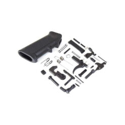
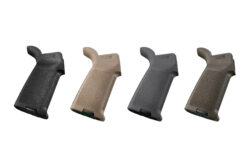

91. Rear Takedown Pin
As one of two pivotal components, the rear takedown pin plays a vital role in securing the upper and lower receivers together in the firearm assembly.
- Function: The rear takedown pin serves as a pivot point, enabling the seamless detachment and reattachment of the upper and lower receivers during assembly, disassembly, and maintenance of the firearm.
- Operation: When installed, the rear takedown pin securely holds the upper and lower receivers in place, ensuring the structural integrity of the firearm. Removal of the pin allows for the separation of the receivers, granting access to internal components for cleaning, lubrication, or customization.
- Design: Rear takedown pins are typically cylindrical in shape, featuring a grooved or knurled surface for ease of manipulation. Equipped with a spring-loaded detent mechanism, they offer secure retention within the lower receiver while facilitating quick and tool-less removal when necessary.
- Installation: The rear takedown pin is inserted through corresponding holes in both the upper and lower receivers, effectively linking them together. Proper alignment and engagement ensure the stability and functionality of the firearm.
- Material: Rear takedown pins are commonly crafted from robust materials such as steel or aluminum, providing durability and resilience to withstand the rigors of firearm operation.
- Maintenance: Regular inspection and upkeep of the rear takedown pin are essential to sustain its reliability. This involves checking for wear, damage, or deformation and promptly addressing any issues to uphold optimal performance.
By securely anchoring the upper and lower receivers, the rear takedown pin facilitates the cohesive operation and integrity of the firearm, enabling smooth assembly and disassembly processes for maintenance and customization purposes.
92. Safety Detent
93. Safety Detent Spring
This essential spring within the firearm's lower receiver applies pressure to the safety detent, ensuring its proper engagement with the safety selector.
- Function: The primary function of the safety detent spring is to generate tension on the safety detent, enabling it to engage with the safety selector and maintain the selected firing mode securely.
- Operation: When the safety selector is moved between safe and fire/live positions, the safety detent spring exerts pressure on the safety detent, causing it to interact with corresponding notches or grooves on the safety selector, thereby indicating the selected firing mode.
- Design: Safety detent springs are typically coiled springs made from high-quality spring steel, engineered to provide consistent tension and reliable operation over time.
- Installation: The safety detent spring is installed within the lower receiver of the firearm, positioned to apply pressure on the safety detent. Proper installation ensures that the detent engages with the safety selector effectively.
- Maintenance: Regular inspection and maintenance of the safety detent spring are important to ensure its continued effectiveness. This includes checking for signs of wear, fatigue, or damage, and addressing any issues promptly to maintain optimal tension and functionality.
- Safety Note: Care should be taken when handling the safety detent spring and other internal components of the firearm to prevent damage and ensure safe and proper function.
By providing the necessary pressure on the safety detent, the safety detent spring plays a critical role in ensuring the reliable operation of the safety selector, enhancing safety and control during firearm handling and operation.
94. Lock Washer
This crucial component serves as a key element in maintaining the secure positioning of the Pistol Grip Screw within the firearm's assembly.
- Function: The primary function of the lock washer is to prevent the Pistol Grip Screw from loosening over time due to vibrations or other external forces. It achieves this by creating additional resistance against rotation, thereby enhancing the stability of the Pistol Grip Screw.
- Design: Lock washers are typically designed with a split-ring or toothed configuration, allowing them to bite into the surface material and create a locking effect when the Pistol Grip Screw is tightened. This design ensures a reliable grip and prevents unintentional loosening.
- Installation: The lock washer is positioned between the head of the Pistol Grip Screw and the surface of the pistol grip or lower receiver. When the Pistol Grip Screw is tightened, the lock washer compresses, creating friction that helps secure the screw in place.
- Material: Lock washers are commonly made from durable materials such as spring steel or stainless steel, ensuring resilience against wear, corrosion, and deformation over time.
- Maintenance: Regular inspection and maintenance of the lock washer are essential to ensure its continued effectiveness. This includes checking for signs of wear, damage, or improper compression and replacing the lock washer if necessary to maintain proper functionality.
By providing a reliable locking mechanism, the lock washer enhances the stability and safety of the Pistol Grip Screw, ensuring that the pistol grip remains securely attached to the lower receiver during firearm operation.
95. Pistol Grip Screw
This pistol grip screw is a crucial component used to secure the pistol grip onto the lower receiver of the firearm, ensuring stability and proper alignment during operation.
- Function: The primary function of the pistol grip screw is to firmly fasten the pistol grip to the lower receiver, providing a secure and stable grip for the shooter.
- Installation: The pistol grip screw is inserted through the bottom of the pistol grip and threaded into the lower receiver, securely holding the grip in place. Proper installation ensures that the grip is firmly attached and properly aligned with the firearm's lower receiver.
- Material: Pistol grip screws are typically made from durable materials such as steel or aluminum, providing strength and reliability to withstand the stresses encountered during firearm operation.
- Design: Pistol grip screws may feature different head types, such as Phillips, Allen, or flat-head, depending on the specific design of the firearm and the preferences of the user. The screw threads are designed to securely engage with the corresponding threads in the lower receiver.
- Maintenance: Regular inspection and maintenance of the pistol grip screw are important to ensure its continued effectiveness. This includes checking for signs of wear, corrosion, or loosening, and tightening or replacing the screw as necessary to maintain proper grip function.
By securely fastening the pistol grip to the lower receiver, the pistol grip screw ensures a stable and comfortable grip for the shooter, enhancing control and accuracy during firearm use.
96. Hammer and Trigger Pins
97. Hammer Spring
The primary function of the hammer spring is to store and release energy, powering the forward movement of the hammer when the trigger is pulled, striking the firing pin and igniting the cartridge.
- Operation: When the trigger is pulled, it releases the sear, allowing the compressed hammer spring to expand rapidly. This expansion drives the hammer forward, causing it to strike the firing pin and discharge the firearm.
- Design: Hammer springs are typically coiled springs made from high-quality spring steel, engineered to withstand repeated compression and maintain their resilience over time.
- Installation: The hammer spring is installed within the lower receiver of the firearm, securely positioned to engage with the hammer assembly. Proper installation ensures that the spring applies the necessary force to the hammer for reliable firing.
- Maintenance: Regular inspection and maintenance of the hammer spring are important to ensure its continued effectiveness. This includes checking for signs of wear, fatigue, or damage, and addressing any issues promptly to maintain optimal performance.
- Safety Note: Care should be taken when handling the hammer spring and other internal components of the firearm to prevent damage and ensure safe and proper function.
By providing the energy to drive the hammer forward, the hammer spring is a critical component in the firing mechanism of the firearm, ensuring reliable ignition of the cartridge and safe operation during use.
98. Safety Selector
Positioned on the lower receiver of the firearm, the safety selector is a critical component for controlling the weapon's firing mode, allowing the shooter to switch between safe and fire/live positions.
- Function: The safety selector enables the shooter to engage or disengage the firearm's firing mechanism, preventing accidental discharge when engaged in the safe position and allowing firing when in the fire/live position.
- Operation: When the safety selector is in the safe position, it blocks the trigger mechanism, preventing it from engaging with the hammer or striker, thus ensuring that the firearm cannot be fired. When the safety selector is moved to the fire/live position, it allows the trigger mechanism to operate normally, enabling firing.
- Design: Safety selectors typically feature a lever or switch that can be easily manipulated by the shooter's thumb or finger, allowing for quick and intuitive switching between safe and fire/live modes. Some safety selectors may also include additional markings or indicators to denote the selected mode.
- Installation: Safety selectors are installed within the lower receiver of the firearm, securely fastened in place with a selector detent and spring, and positioned to properly engage with the trigger mechanism.
- Material: Safety selectors are commonly made from durable materials such as steel or aluminum, ensuring strength and reliability under the stresses of firearm operation.
- Maintenance: Regular inspection and maintenance of the safety selector are important to ensure its continued effectiveness. This includes checking for signs of wear, damage, or debris buildup, and addressing any issues promptly to maintain optimal functionality.
By providing a convenient and reliable means of controlling the firearm's firing mode, the safety selector enhances safety and control during firearm handling and operation, reducing the risk of accidental discharge and ensuring responsible firearm use.
99. Bolt Catch
This integral component of the firearm's lower receiver serves two main functions: capturing and holding the bolt in the rearward position and serving as the lever to release it.
- Capture Function: When the firearm's bolt carrier group moves rearward after firing, the AR-15 bolt catch engages with the bolt, capturing and holding it in the open or rearward position, facilitating magazine changes or inspection of the chamber.
- Release Lever: Additionally, the bolt catch features a lever or paddle that protrudes from the lower receiver, allowing the shooter to manually release the bolt and chamber a new round when inserting a loaded magazine into the firearm.
- Design: Bolt catches typically consist of a lever or paddle connected to a mechanism within the lower receiver, designed to engage with the bolt carrier group and lock it in place when the bolt is in the rearward position.
- Installation: Bolt catches are installed within the lower receiver of the firearm, securely fastened in place with a bolt catch roll pin and positioned to properly engage with the bolt carrier group.
- Material: Bolt catches are commonly made from durable materials such as steel or aluminum, ensuring strength and reliability under the stresses of firearm operation.
- Maintenance: Regular inspection and maintenance of the bolt catch are important to ensure its continued effectiveness. This includes checking for signs of wear, damage, or debris buildup, and addressing any issues promptly to maintain optimal functionality.
By capturing and holding the bolt in the rearward position and providing a lever for its manual release, the bolt catch plays a crucial role in the reliable operation of the firearm, facilitating magazine changes and ensuring smooth cycling during use.
100. Bolt Catch Roll Pin
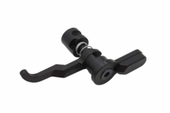
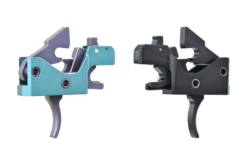
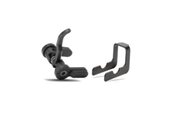
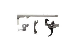
101. Bolt Catch Plunger
102. Bolt Catch Spring
This spring applies pressure to the bolt catch mechanism, facilitating its proper function within the firearm's operating system.
- Function: The primary function of the AR-15 bolt catch spring is to exert pressure on the bolt catch, ensuring it remains in its engaged or disengaged position as needed during firearm operation.
- Operation: When the bolt is locked back, the bolt catch spring applies tension to keep the bolt catch in its raised position, holding the bolt open. When the bolt is released, the bolt catch spring assists in returning the bolt catch to its lowered position, allowing the bolt to close and chamber a new round.
- Design: Bolt catch springs are typically made from durable spring steel and are designed to provide consistent tension over time, ensuring reliable operation of the bolt catch mechanism.
- Installation: The bolt catch spring is installed within the lower receiver of the firearm, typically positioned in conjunction with the bolt catch assembly. Proper installation is essential to ensure the spring applies the necessary tension to the bolt catch.
- Maintenance: Regular inspection and maintenance of the bolt catch spring are important to ensure its continued effectiveness. This includes checking for signs of wear, fatigue, or damage, and addressing any issues promptly to maintain optimal tension and functionality.
By providing the necessary tension for the bolt catch mechanism, the bolt catch spring plays a critical role in the reliable operation of the firearm, ensuring smooth cycling and proper functioning during use.
103. Magazine Catch
The primary function of the AR-15 magazine catch is to engage with the magazine's locking mechanism, securely holding it in position within the firearm's magazine well.
- Operation: When the shooter presses the magazine catch button, the magazine catch disengages from the magazine, allowing it to be easily inserted or removed from the firearm. Upon release of the button, the magazine catch locks into place, securing the magazine in the magazine well.
- Design: Magazine catches come in various designs, including ambidextrous and extended versions, offering enhanced ergonomics and ease of operation for shooters with different hand sizes and preferences.
- Compatibility: Magazine catches are often interchangeable and compatible with different firearm models, allowing shooters to customize their weapons according to personal preference or ergonomic requirements.
- Installation: Magazine catches are typically installed onto the lower receiver of the firearm, securely fastened to ensure proper alignment and function with the magazine's locking mechanism.
- Maintenance: Regular inspection and maintenance of the magazine catch are important to ensure its continued effectiveness. This includes checking for signs of wear, damage, or improper alignment, and addressing any issues promptly to maintain smooth operation.
By securely retaining the magazine within the firearm's magazine well, the magazine catch enhances the reliability and functionality of the firearm, ensuring smooth magazine changes during shooting sessions.
104. Pivot Pin Spring
This small yet essential spring provides the tension necessary to secure the pivot pin detent in place, ensuring the proper retention of the pivot pin within the firearm's lower receiver.
- Function: The primary function of the AR-15 pivot pin spring is to apply pressure to the pivot pin detent, ensuring it engages with the pivot pin and maintains its position, thereby securing the pivot pin in place during firearm operation.
- Role: Working in conjunction with the pivot pin detent, the pivot pin spring creates tension that keeps the pivot pin securely seated within its designated position, preventing unintentional disengagement or rotation.
- Installation: The pivot pin spring is typically installed within a recess in the lower receiver, positioned to exert pressure on the pivot pin detent. This ensures proper retention of the pivot pin assembly within the firearm's lower receiver.
- Maintenance: Regular inspection and maintenance of the pivot pin spring are important to ensure its continued effectiveness. This includes checking for signs of wear, fatigue, or damage, and addressing any issues promptly to maintain optimal tension and retention of the pivot pin assembly.
- Safety Note: Care should be taken when handling the pivot pin spring and pivot pin detent assembly to prevent loss of components and ensure proper installation.
By providing the necessary tension to secure the pivot pin detent in place, the pivot pin spring plays a crucial role in maintaining the stability and functionality of the firearm's upper and lower receiver assembly, contributing to safe and reliable operation.
105. Pivot Pin Detent
This small but vital component secures the pivot pin in place within the firearm's lower receiver, working in conjunction with the pivot pin spring to maintain proper alignment and retention.
- Function: The primary function of the pivot pin detent is to engage with the pivot pin, preventing it from unintentionally disengaging or rotating out of position while the firearm is in use.
- Role: Working in tandem with the pivot pin spring, the pivot pin detent ensures that the pivot pin remains securely seated in its designated position, maintaining the structural integrity and alignment of the firearm's upper and lower receivers.
- Installation: The pivot pin detent is typically installed within a recess in the lower receiver, positioned to engage with the corresponding notch or groove on the pivot pin. This ensures proper alignment and retention of the pivot pin during operation.
- Maintenance: Regular inspection and maintenance of the pivot pin detent are important to ensure its continued effectiveness. This includes checking for signs of wear, debris buildup, or damage, and addressing any issues promptly to maintain optimal functionality.
- Safety Note: Care should be taken when disassembling or reassembling the pivot pin detent and pivot pin assembly to prevent loss of components and ensure proper installation.
By securely engaging with the pivot pin, the pivot pin detent plays a critical role in maintaining the stability and functionality of the firearm's upper and lower receiver assembly, contributing to reliable operation and user safety.
106. Pivot Pin
The primary function of the AR-15 pivot pin is to maintain alignment and structural integrity between the upper and lower receivers while allowing for easy access to the internal components of the firearm.
- Design: Pivot pins typically feature a spring-loaded detent mechanism that ensures secure retention in the closed position while allowing for quick and tool-less disassembly when necessary.
- Access: By pivoting the upper receiver upward about the pivot pin, shooters can access the internal components of the firearm, such as the bolt carrier group and buffer assembly, for cleaning, lubrication, or maintenance without the need for complete disassembly.
- Installation: Pivot pins are installed through corresponding holes in the upper and lower receivers, securely fastened to maintain the alignment and stability of the firearm's components.
- Maintenance: Regular inspection and maintenance of the pivot pin are important to ensure its continued effectiveness. This includes checking for signs of wear, corrosion, or damage, and addressing any issues promptly to maintain optimal functionality.
- Safety Note: When reinstalling the pivot pin after maintenance, care should be taken to ensure proper alignment and engagement to prevent damage to the firearm's components and ensure safe operation.
By facilitating easy access to the internal components of the firearm, the pivot pin enhances the convenience and efficiency of maintenance tasks, contributing to the overall reliability and longevity of the firearm.
107. Magazine Catch Button
The magazine catch button, typically located on the lower receiver of the firearm, serves as the interface for releasing the magazine from the firearm when depressed.
- Function: The primary function of the magazine catch button is to actuate the release mechanism of the magazine catch, allowing the magazine to be easily removed from the firearm for reloading.
- Operation: When the shooter depresses the magazine catch button, it disengages the magazine catch, allowing the magazine to drop free or be removed manually from the firearm's magazine well.
- Design: Magazine catch buttons come in various designs, including textured or grooved surfaces for enhanced grip and tactile feedback, ensuring easy operation even in adverse conditions or with gloved hands.
- Compatibility: Magazine catch buttons are often interchangeable and compatible with different firearm models, allowing shooters to customize their weapons according to personal preference or ergonomic requirements.
- Installation: Magazine catch buttons are typically installed onto the lower receiver of the firearm, securely fastened to ensure proper alignment and function with the magazine catch mechanism.
- Maintenance: Regular inspection and maintenance of the magazine catch button are important to ensure its continued effectiveness. This includes checking for signs of wear, damage, or improper alignment, and addressing any issues promptly to maintain smooth operation.
By providing a convenient and reliable means of releasing the magazine from the firearm, the magazine catch button enhances the ease of reloading and overall usability of the firearm during shooting sessions.
108. Magazine Catch Spring
The magazine catch spring generates tension to secure the magazine catch in place, preventing accidental release of the magazine from the firearm.
- Material: Typically crafted from durable spring steel, the magazine catch spring is designed to withstand repeated compression and maintain its tension over time.
- Function: The primary function of the magazine catch spring is to exert pressure on the magazine catch, ensuring it remains engaged with the magazine until intentionally released by the shooter.
- Security: By applying tension to the magazine catch, the magazine catch spring prevents unintentional disengagement of the magazine, ensuring that it remains securely seated within the firearm during use.
- Release Mechanism: When the shooter depresses the magazine catch, the tension from the magazine catch spring is overcome, allowing the magazine to be released from the firearm for reloading.
- Installation: Proper installation of the magazine catch spring is essential for ensuring its effectiveness. It must be correctly positioned within tMaintenance: Regular inspection and maintenance of the magazine catch spring are important to ensure its continued effectiveness. This includes checking for signs of wear, fatigue, or damage, and addressing any issues promptly to maintain optimal tension.
By creating tension to secure the magazine catch in place, the magazine catch spring enhances the reliability and safety of the firearm, preventing accidental release of the magazine and ensuring smooth reloading during use.
109. Trigger Guard Pivot Roll Pin
This small yet essential roll pin serves a dual purpose in securing the rear of the trigger guard and acting as a pivot point for the guard, facilitating its movement for maintenance or cleaning tasks.
- Material: Typically fabricated from durable metal, such as steel or aluminum, the trigger guard pivot roll pin provides strength and stability for the trigger guard assembly.
- Function: The primary function of the trigger guard pivot roll pin is to securely fasten the rear of the trigger guard to the lower receiver of the firearm, ensuring proper alignment and stability during operation. Additionally, it allows the trigger guard to pivot when necessary, providing access to the firearm's internal components for maintenance or cleaning.
- Installation: The trigger guard pivot roll pin is inserted through the trigger guard assembly and the lower receiver, securely fastening the trigger guard in place while allowing it to pivot as needed.
- Maintenance: Regular inspection and maintenance of the trigger guard pivot roll pin are important to ensure its continued effectiveness. This includes checking for signs of wear, corrosion, or damage, and addressing any issues promptly to maintain optimal functionality.
- Safety Note: When removing or reinstalling the trigger guard pivot roll pin, care should be taken to avoid damaging the firearm's components, and proper techniques and tools should be used to ensure safe and secure installation.
By securely holding the trigger guard in place and enabling its pivoting movement, the trigger guard pivot roll pin facilitates convenient access to the firearm's internal components for maintenance or cleaning, enhancing the overall usability and functionality of the firearm.
110. Trigger Guard Assembly
AR-15 Trigger guard assemblies are commonly constructed from a variety of materials, including polymer, metal, or integrated directly into the lower receiver itself, providing durability and protection to the trigger mechanism.
- Function: The primary function of the trigger guard assembly is to safeguard the trigger from impacts, debris, or accidental contact, ensuring the integrity and functionality of the firearm's firing mechanism.
- Design: Trigger guard assemblies come in various designs, ranging from traditional trigger guards to enlarged or extended versions that accommodate gloved hands or enhance ergonomics for improved handling.
- Compatibility: Trigger guard assemblies are often interchangeable and compatible with different firearm models, allowing shooters to customize their weapons according to personal preference and shooting requirements.
- Installation: Trigger guard assemblies are typically installed onto the firearm's lower receiver or trigger assembly, securely fastened to provide a protective barrier around the trigger mechanism.
- Maintenance: Regular inspection and maintenance of the trigger guard assembly are important to ensure its continued effectiveness. This includes checking for signs of wear, corrosion, or damage, and addressing any issues promptly to maintain optimal protection.
By providing a protective barrier around the trigger mechanism, the trigger guard assembly enhances the safety and durability of the firearm, minimizing the risk of damage or malfunction during use.
111. Trigger
As the final interface between the shooter and the firearm, the AR-15 trigger is the crucial component responsible for initiating the firing sequence, ultimately propelling the projectile forward.
- Function: The primary function of the trigger is to release the hammer or striker, which then strikes the firing pin, igniting the primer and firing the cartridge.
- Operation: When the trigger is pulled, it disengages the sear, allowing the hammer or striker to move forward under spring tension. Upon release, the hammer or striker strikes the firing pin, initiating the ignition process.
- Design: Triggers come in various designs, including single-stage and two-stage triggers, each offering different characteristics such as trigger pull weight and travel distance to suit the shooter's preferences.
- Safety: Proper trigger discipline, including keeping the finger off the trigger until ready to fire, is essential for safe firearm handling and prevention of accidental discharges.
- Compatibility: Triggers are often interchangeable and compatible with different firearm models, allowing shooters to customize their weapons according to personal preference and shooting style.
- Installation: Triggers are typically installed within the firearm's lower receiver or trigger assembly, ensuring proper alignment and function with other internal components.
- Maintenance: Regular inspection and maintenance of the trigger are important to ensure its continued reliability and performance. This includes checking for signs of wear, cleaning, and lubricating as necessary.
By initiating the firing sequence, the trigger is the critical link between the shooter and the firearm, ultimately determining the timing and precision of each shot fired.
112. Disconnector Spring
113. Disconnector
The AR-15 Disconnector in semi-automatic firearms serves two primary purposes, ensuring safe and controlled firing sequences.
- Function: The disconnector's first function is to disconnect the trigger from the sear (hammer or striker) after each shot is fired. This action prevents automatic firing and ensures the firearm operates in a semi-automatic mode, requiring the trigger to be released and reset before the next shot can be fired.
- Safety: By disengaging the trigger from the sear after each shot, the disconnector helps prevent unintended or automatic firing, enhancing firearm safety and compliance with regulations governing semi-automatic firearms.
- Reset: The second function of the disconnector is to allow the trigger to reset fully before another shot can be fired. This ensures proper sequencing of the firing mechanism and maintains the firearm's semi-automatic operation.
- Installation: The disconnector is typically installed within the trigger assembly of the firearm and interacts with other internal components such as the trigger and sear.
- Maintenance: Regular inspection and maintenance of the disconnector are important to ensure its continued effectiveness. This includes checking for wear, damage, or improper alignment that may affect its function.
- Safety Note: It's important to understand that simply removing the disconnector will not convert a semi-automatic firearm into an automatic one. Other modifications and illegal alterations would be necessary to achieve full automatic firing, which is illegal and highly unsafe.
By disengaging the trigger from the sear and ensuring proper reset, the disconnector plays a crucial role in maintaining the safe and controlled operation of semi-automatic firearms.
114. Trigger Spring
115. Pistol Grip
The AR-15 Pistol Grip serves as the primary point of contact for the shooter's hand that controls the trigger, providing a comfortable and ergonomic grip for improved handling and control of the firearm.
- Material: Pistol grips are commonly crafted from a variety of materials, including polymer, wood, and metal, offering different aesthetics, textures, and weights to suit the preferences and needs of the shooter.
- Function: The primary function of the pistol grip is to provide a secure and stable grasp for the shooter's hand, enhancing control and accuracy during firearm operation.
- Design: Pistol grips come in various designs, ranging from traditional to ergonomic shapes, with features such as finger grooves, palm swells, and textured surfaces to optimize grip comfort and control.
- Compatibility: Pistol grips are often interchangeable and compatible with different firearm models, allowing shooters to customize their weapons according to personal preference and shooting style.
- Installation: Pistol grips are typically attached to the firearm's lower receiver using screws or other fastening mechanisms, ensuring a secure and stable connection.
- Maintenance: Regular inspection and maintenance of the pistol grip are important to ensure its continued functionality and comfort. This includes cleaning, lubricating moving parts, and checking for any signs of wear or damage.
By providing a comfortable and ergonomic grip, the pistol grip enhances the shooter's control and accuracy, contributing to a more enjoyable and effective shooting experience.
116. Magazine Box
This component forms the exterior shell or enclosure of the magazine, providing containment for the ammunition and internal components.
Material: Traditionally constructed from metal, such as steel or aluminum, older magazine boxes offer durability and rigidity. However, newer iterations often utilize unibody polymer construction, enhancing lightweight and corrosion resistance.
- Function: The primary function of the magazine box is to house the ammunition stack and internal components, safeguarding them from external elements and ensuring smooth feeding into the firearm.
- Variants: Modern magazine boxes, especially those made from polymer, may integrate features such as reinforced feed lips and anti-tilt followers to enhance reliability and longevity.
- Role in Operation: Integral to the functionality of the magazine, the magazine box maintains the structural integrity of the assembly, providing a stable platform for the ammunition and internal components.
- Maintenance: While metal magazine boxes may require occasional lubrication and rust prevention measures, polymer magazine boxes generally offer low maintenance requirements due to their corrosion-resistant properties.
- Customization: Some magazine boxes may feature interchangeable base plates or grip extensions, allowing users to tailor the magazine to their preferences or accommodate different firearm platforms.
By enclosing the ammunition and internal components, the magazine box ensures reliable feeding and operation of the firearm, contributing to its overall functionality and performance.
117. Magazine Floor Plate
Positioned at the bottom of the magazine, the floor plate serves as the platform against which the magazine spring exerts pressure, ensuring proper tension for reliable feeding of ammunition.
- Material: Typically composed of durable materials such as steel, aluminum, or polymer, the magazine floor plate provides structural support and stability to the magazine assembly.
- Function: The primary function of the magazine floor plate is to secure the magazine spring and follower within the magazine body, while also allowing for disassembly and maintenance when necessary.
- Role in Operation: Integral to the functionality of the magazine, the floor plate holds the components in place, ensuring consistent tension from the magazine spring to feed ammunition into the firearm reliably.
- Installation: Proper installation of the magazine floor plate is essential for maintaining the integrity and functionality of the magazine assembly. It must be securely attached to the magazine body to prevent any movement or dislodgement during use.
- Maintenance: Regular inspection and maintenance of the magazine floor plate are important to ensure its continued effectiveness. This includes checking for signs of wear, corrosion, or damage, and addressing any issues promptly to maintain optimal performance.
By securely housing the magazine spring and follower, the magazine floor plate plays a critical role in the reliable feeding of ammunition into the firearm, contributing to its overall functionality and performance.
118. Magazine Follower
This integral component of the magazine serves as the surface against which the ammunition rests, applying pressure to the remaining rounds and ensuring they are properly positioned at the top of the magazine for feeding into the firearm.
- Material: Typically made from durable materials such as polymer or metal, the magazine follower is engineered to withstand the forces exerted by the spring and maintain consistent pressure on the ammunition stack.
- Function: The primary function of the magazine follower is to provide a smooth and even surface for the ammunition to rest against, while also guiding the cartridges into position as they are fed into the firearm.
- Role in Operation: Essential to the reliable function of the magazine, the magazine follower ensures that the ammunition remains properly aligned and ready for feeding into the firearm's chamber during operation.
- Installation: Proper installation of the magazine follower is crucial for ensuring its effectiveness. It must be correctly positioned within the magazine body to provide smooth movement and consistent pressure on the ammunition stack.
- Maintenance: Regular inspection and maintenance of the magazine follower are important to ensure its continued effectiveness. This includes checking for signs of wear, damage, or deformation, and addressing any issues promptly to maintain optimal performance.
By guiding and applying pressure to the ammunition stack, the magazine follower plays a critical role in the reliable feeding of ammunition into the firearm, enhancing its functionality and performance.
119. Magazine Spring
This vital spring is responsible for generating the tension necessary to hold the ammunition cartridges in place at the top of the magazine, ready for feeding into the firearm.
- Material: Typically manufactured from durable and resilient spring steel, the magazine spring is designed to withstand repeated compression and maintain its tension over time.
- Function: The primary function of the magazine spring is to apply consistent pressure to the stack of cartridges within the magazine, ensuring they remain properly aligned and ready for feeding into the firearm's chamber.
- Role in Operation: Integral to the reliable function of the magazine, the magazine spring ensures smooth and consistent feeding of ammunition into the firearm during operation, contributing to its overall reliability and performance.
- Installation: Proper installation of the magazine spring is essential for ensuring its effectiveness. It must be correctly positioned within the magazine body to exert the appropriate tension on the cartridges.
- Maintenance: Regular inspection and maintenance of the magazine spring are important to ensure its continued effectiveness. This includes checking for signs of wear, fatigue, or damage, and replacing the spring if necessary to maintain optimal tension.
By creating the tension necessary to hold the ammunition in place, the magazine spring plays a critical role in the reliable feeding of ammunition into the firearm, enhancing its functionality and performance.
Empower Your AR-15 Maintenance with Black Rifle Depot's Comprehensive Parts Diagram and Resources
When it comes to maintaining your AR-15 rifle, having a reliable reference is invaluable, and the AR-15 parts diagram available from Black Rifle Depot is an excellent guide. This diagram provides a comprehensive overview of your rifle's components and intricate interconnections, making it easier to understand how each part functions within the firearm. Utilizing this diagram as a reference during maintenance tasks, such as cleaning, lubrication, or even troubleshooting, you gain a deeper insight into your rifle's inner workings, ensuring thorough and effective care. Additionally, Black Rifle Depot offers a wide selection of replacement parts and tools tailored specifically for the AR-15 platform. From small components like springs and pins to essential tools for assembly and maintenance, Black Rifle Depot provides everything you need to keep your AR-15 rifle in top condition. With the AR-15 parts diagram and quality replacement parts from Black Rifle Depot, you have the resources to confidently maintain your rifle, ensuring its reliability and longevity for years to come.